Strain relief boot for cable connector

a cable connector and cable technology, applied in the direction of optical elements, coupling device connections, instruments, etc., can solve the problems of excessive bending of cables, affecting the transmission characteristics of fibers, and reducing optical performance, so as to prevent undesirable degradation of optical performance

Inactive Publication Date: 2010-03-16
TE CONNECTIVITY CORP
View PDF67 Cites 64 Cited by
  • Summary
  • Abstract
  • Description
  • Claims
  • Application Information

AI Technical Summary

Benefits of technology

[0007]An embodiment of the present invention provides a strain relief boot that is capable of enduring a wide range of side loads, e.g. 0-3 pounds, and that limits a cable bend radius, e.g. to prevent undesirable degradation of optical performance of a corresponding fiber optic cable. The strain relief boot is constructed to provide a staged bending characteristic in that there is a first discrete zone configured to bend at lower side loads, and a second discrete zone configured to bend at higher side loads. Preferably, each zone has a different minimum bend radius. A connector assembly, such as a fiber optic connector assembly, including such a strain relief boot is provided also.

Problems solved by technology

Cables may be subject to excessive bending when side loads are placed on the cable.
Excessive bending of the fiber negatively impacts the transmission characteristics of the fiber and degrades optical performance.
While some strain relief devices and / or connectors may be suitable for certain applications, e.g. where there is ample environmental space, they are unsuitable for applications in which space is limited.
Due to the combined length of existing strain relief devices and connectors, there is sometimes insufficient clearance space between a front face of the components and an inside face of the cover when the cover is closed.
As a result, the cover cannot be closed, or optical performance is degraded as the closed cover impinges upon the strain relief devices and causes bending of the fiber / strain relief device.

Method used


Image

  • Strain relief boot for cable connector
  • Strain relief boot for cable connector
  • Strain relief boot for cable connector

Examples


Embodiment Construction

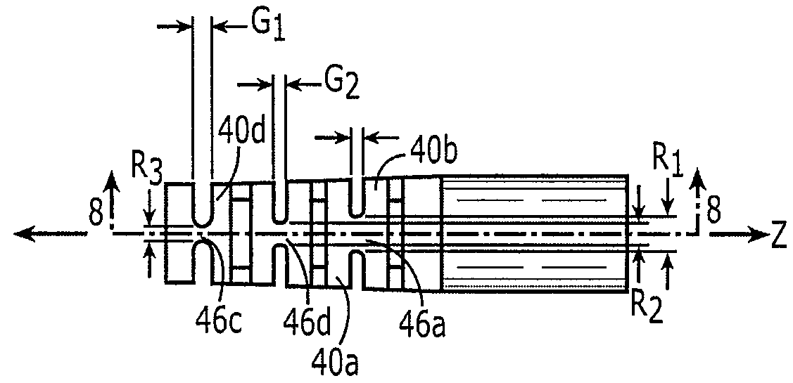
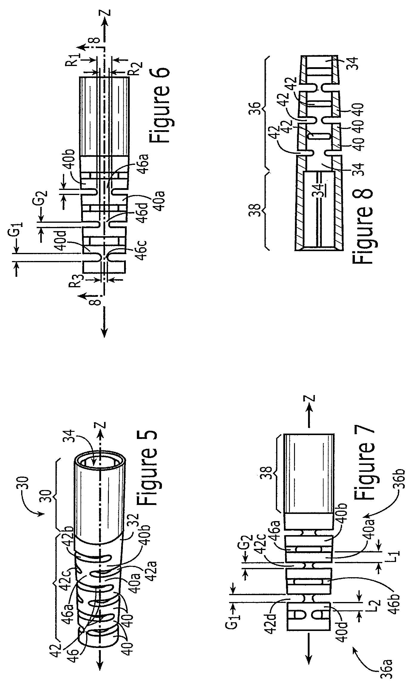
[0030]An embodiment of the present invention provides a segmented strain relief boot that is capable of enduring a wide range of side loads, e.g. 0-3 pounds, and that limits a cable bend radius, e.g. to prevent undesirable degradation of optical performance of a corresponding fiber optic cable. More specifically, the strain relief boot provides a staged bending characteristic in that there is a first discrete zone configured to bends at lower side loads, and a second discrete zone configured to bend at higher side loads. Preferably, each zone has a different minimum bend radius. A cable connector assembly including such a strain relief boot is provided also.

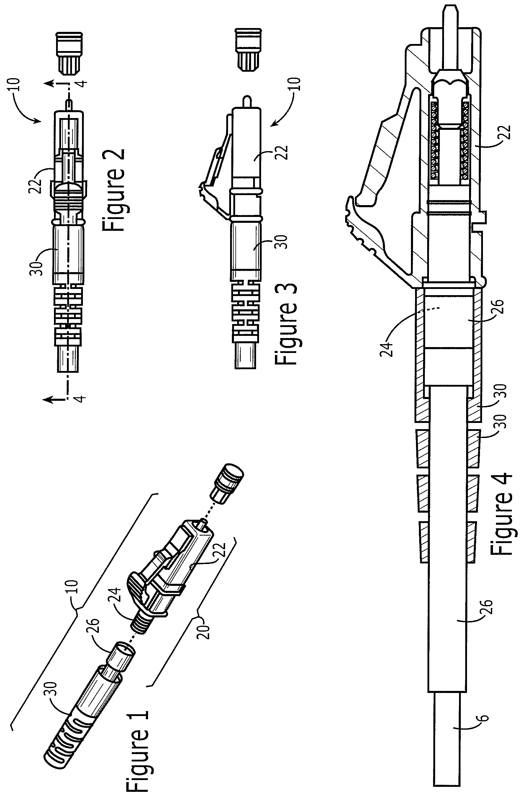
[0031]Referring now to FIGS. 1-4, an exemplary fiber optic cable assembly 10 is shown that includes a connector 20 for connecting a cable to a receptacle, and an exemplary strain relief boot 30 in accordance with the present invention. In this exemplary embodiment, the connector 20 is an LC style fiber optic connector. The exempl...


PUM


Abstract

A strain relief boot for a connectorized cable. The boot has a staged bending characteristic in that there are discrete first and second zones that have different bending and minimum bend radius characteristics. The boot is of a segmented design including multiple links separated from one another by open gaps that are spaced from one another in a longitudinal direction. Gaps are positioned along a periphery of the boot for each axial location. Ribs extend longitudinally to connect axially adjacent links, and to separate peripherally spaced gaps. The different characteristics relate to differences in the gap, link and rib structures, which have dimensions varying along the boot's length. Preferably, link and rib dimensions are relatively smaller toward a proximal end of the boot, and gap dimensions are relatively larger toward the proximal end of the boot. This provides greater flexibility and smaller minimum bend radii toward the boot's proximal end.

Description

FIELD OF THE INVENTION[0001]The present invention relates generally to strain relief for cables, and more particularly to a strain relief boot for a fiber optic or other cable and / or connector.DISCUSSION OF RELATED ART[0002]Cables, including optical fibers, are commonly used in a variety of applications, including telecommunications applications. The fibers may be terminated to any of a variety of different connectors, such as LC, FC, MU, SC and ST type connectors. Such connectors are used to join fibers to active or passive optical components such as sources, detectors, repeaters, switches, attenuators, etc.[0003]Cables may be subject to excessive bending when side loads are placed on the cable. It is well known in the art that particular care is taken in fiber optic cable applications not to violate a minimum bend radius of the cable. Excessive bending of the fiber negatively impacts the transmission characteristics of the fiber and degrades optical performance. Such loads are oft...

Claims


Application Information

Patent Timeline
Patent Type & Authority Patents(United States)
IPC IPC(8): G02B6/38
CPCH01R13/562G02B6/4478
Inventor CASTAGNA, LOUGURRERI, MICHAEL L.KADAR-KALLEN, MICHAEL AARONCORMANY, DAVID
Owner TE CONNECTIVITY CORP
Why Eureka
Try Eureka