Lighter device with flow restrictor and methods of manufacturing and testing same

a technology of flow restrictor and lighter device, which is applied in the direction of fluid tightness measurement, lighting and heating apparatus, instruments, etc., can solve the problems of adding restrictions on the shipment of such lighters, adding to the cost and difficulty of distributing such lighters in commerce, etc., to achieve the effect of maximizing avoiding the cost and difficulty of distributing, and facilitating and enhancing the initial filling of the tank

Active Publication Date: 2010-04-06
ZIPPO MFG
View PDF4 Cites 0 Cited by
  • Summary
  • Abstract
  • Description
  • Claims
  • Application Information

AI Technical Summary

Benefits of technology

[0007]The present disclosure overcomes the cost and difficulty of distributing lighters with fuel by providing an apparatus and method for manufacturing, testing and distributing “dry” lighters having flow restrictors, e.g., lighters having not received a combustible fuel, such as, butane or a butane mixture. An exemplary flow restrictor may be formed of a porous member that regulates the flow of fuel through a valve assembly of the lighter to induce a substantially fixed flame height or a variable flame height. The porous member may be rigid or compressible and may include a single opening or a plurality of openings. The flow restrictor may be tested before or after assembly into a lighter. When tested before assembly, a combustible fuel or a non-combustible fluid (e.g., inert gas) may be directed through the flow restrictor to assess the flow rate. If a non-combustible fluid is used, the flow rate of the non-combustible fluid may be correlated to the flow rate of a combustible fluid (e.g., butane or butane-like mixture) through the flow restrictor to approximate the resultant flame height of a lighter incorporating the tested flow restrictor. When tested after assembly of the flow restrictor into the lighter housing, a non-combustible fluid may be directed through the flow restrictor to assess the flow rate. The flow rate of the non-combustible fluid may be correlated to the flow rate of a combustible fluid through the flow restrictor to approximate the resultant flame height of a lighter incorporating the flow restrictor. In this manner, flow restrictors and corresponding lighter devices may be tested for flame height without introducing combustible fluids into such lighter devices prior to shipment.
[0008]Moreover, a vacuum may be drawn on the fuel tank of the lighter prior to shipment. In embodiments where the flow restrictor is tested after assembly into the lighter, the non-combustible fluid may be extracted from the fuel tank and a vacuum drawn thereon. Providing a refillable lighter with a fuel tank under vacuum would facilitate and enhance the initial filling of the tank with fuel by the consumer, allowing for the fuel to enter the tank without the need to compress the air sealed in the tank during normal manufacturing processes. This allows for the consumer to maximize the initial fill of the tank with fuel, while minimizing internal pressure in the fuel reservoir. This is also advantageous in avoiding pressure increases during transport of lighters in hot climates.

Problems solved by technology

Once the lighter has been filled with fuel, additional restrictions on the shipment of such lighters may be incurred because they may be classified by some entities as hazardous goods.
This adds to the cost and difficulty of distributing such lighters in commerce.

Method used


Image

  • Lighter device with flow restrictor and methods of manufacturing and testing same
  • Lighter device with flow restrictor and methods of manufacturing and testing same
  • Lighter device with flow restrictor and methods of manufacturing and testing same

Examples


Embodiment Construction

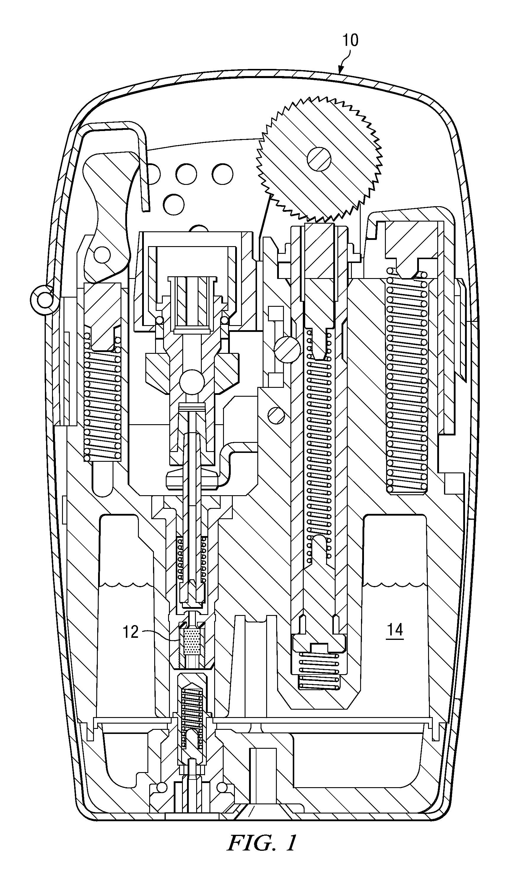
[0021]Referring to FIG. 1, a lighter 10 according to the present disclosure is illustrated. It is to be understood, however, that other forms of lighters may be used as alternatives to the lighter 10 shown in FIG. 1, and that the lighter 10 is presented as an example to illustrate aspects of the present disclosure. Indeed, the lighter 10 may be any lighter device that incorporates a flow restrictor or flow restrictor-like device. The lighter 10 includes a flow restrictor assembly 12, which receives fuel from a fuel storage compartment 14. In practice, a user may initiate a flame by actuating the lighter to induce fluid flow from the storage compartment 14 to and through the flow restrictor assembly 12. As used herein, the term “fluid” refers to fluid in a gaseous state, liquid state, plasma state, or combinations thereof.

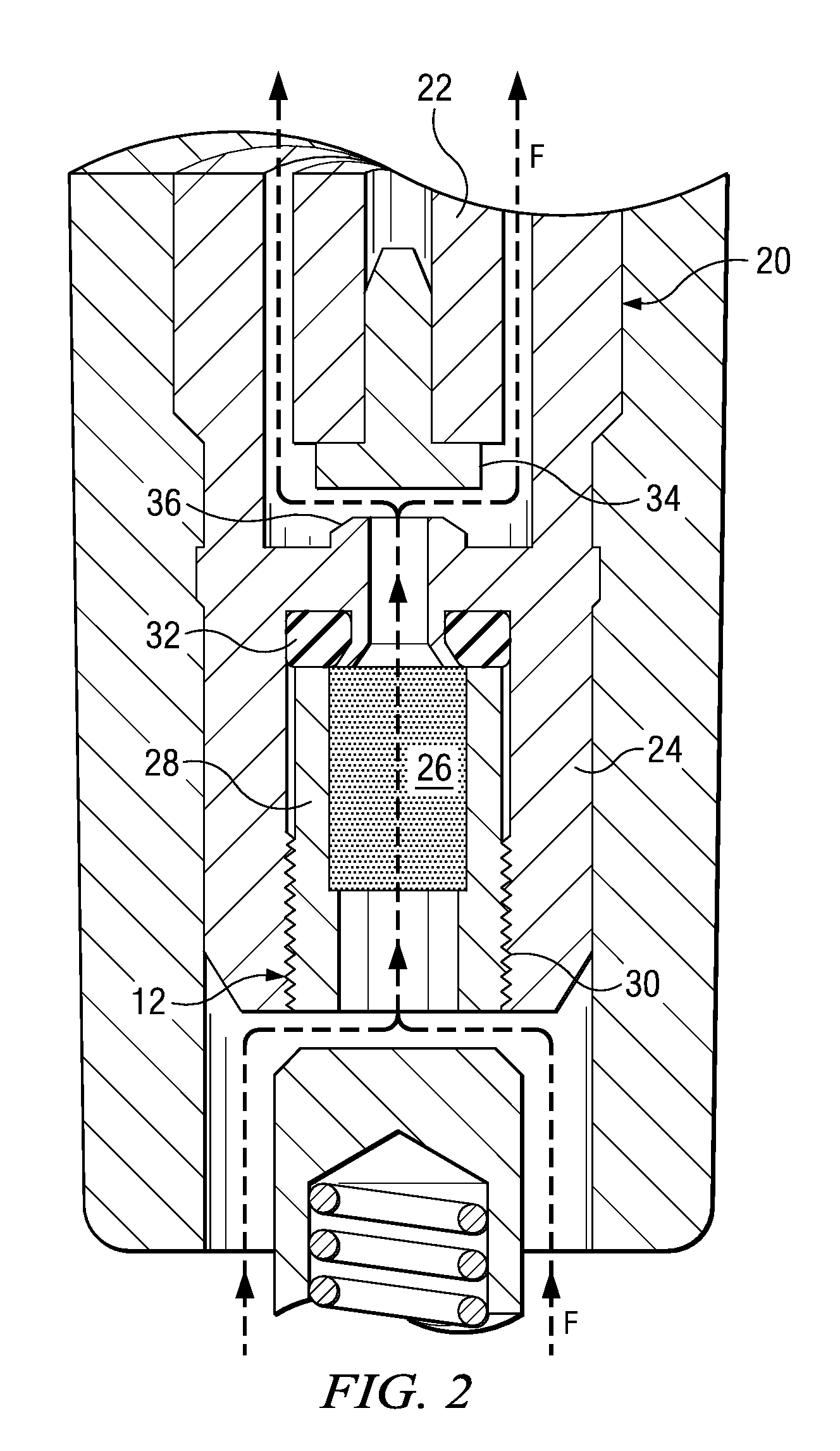
[0022]FIG. 2 details a portion of a valve assembly 20 of the lighter 10. The valve assembly 20 includes a valve member 22 disposed above the flow restrictor assembl...


PUM

PropertyMeasurementUnit
Tgaaaaaaaaaa
flow rateaaaaaaaaaa
flow ratesaaaaaaaaaa

Abstract

A lighter device having a flow restrictor and associated methods for manufacturing and testing such lighter device and flow restrictor are described. The flow restrictor may be formed of a porous member to achieve a substantially fixed or varying flame height. The flow restrictor may be tested before or after assembly into a lighter housing by receiving a non-combustible fluid therethrough. The flow rate of the non-combustible fluid may be correlated to the flow rate of a combustible fluid through the flow restrictor to approximate the resultant flame height of a lighter incorporating the tested flow restrictor. The flow restrictor may also be tested by receiving a combustible fluid therethrough prior to assembling the flow restrictor into the lighter housing. In this manner, flow restrictors and corresponding lighter devices may be tested without introducing combustible fluids into such lighter devices prior to shipment. Also, a vacuum may be drawn on a fuel tank of the lighter prior to shipment.

Description

CROSS-REFERENCE TO RELATED APPLICATIONS[0001]This application claims priority to U.S. Provisional Patent Application No. 60 / 596,731, filed Oct. 17, 2005, entitled “Lighter device with flow restrictor and methods of manufacturing and testing same,” the contents of which are incorporated herein by reference in its entirety.BACKGROUND[0002]1. Technical Field[0003]This disclosure relates to lighter devices, and more particularly to “open flame” lighter devices having a flow restrictor. Related methods of manufacturing and testing open flame lighter devices are also described.[0004]2. Description of Related Art[0005]Open flame lighters are commonly used for igniting tobacco products such as cigarettes, cigars, pipes and the like. Such devices lie in contrast to devices in which a flame is entirely or substantially entirely enclosed, for example, for heating. Many open flame lighters utilize pressurized fuel to induce the flame. Such lighters are commonly referred to as “butane” lighters,...

Claims


Application Information

Patent Timeline
Patent Type & Authority Patents(United States)
IPC IPC(8): G01M3/02G01F25/00G01P21/00
CPCF23Q2/162F23Q23/08F23Q2/163Y10T29/49348G01M3/02
Inventor MCDONOUGH, JAMES M.MEISTER, RONALD J.JOHNSON, MICHAEL W.
Owner ZIPPO MFG
Why Eureka
Try Eureka