Combat vehicle restraint system

a technology for occupants and restraints, applied in the direction of pedestrian/occupant safety arrangements, vehicular safety arrangements, safety belts, etc., can solve the problems of affecting the effective harness operation, not being easy to use or provide the desired occupant protection, and causing occupant injuries, etc., to prevent gear from catching, easy to find and adjust, and easy to adjus

Active Publication Date: 2010-05-25
COBHAM MISSION SYST DAVENPORT LSS INC
View PDF32 Cites 25 Cited by
  • Summary
  • Abstract
  • Description
  • Claims
  • Application Information

AI Technical Summary

Benefits of technology

[0005]The present invention addresses the above and other needs by providing a combat vehicle restraint system which accommodates a wide range of soldiers, both with and without battle, arctic, or chemical gear. The restraint system includes lengthened belts and an adjustable buckle position. The belts include loops for locating and grasping the belts, and separate lap and shoulder belts with small narrowing ends to prevent catching on gear. The belts are extendable from inertial reels which are calibrated for off-road operation. The buckle engages each belt separately and includes a single action release. The buckle position is easily adjusted using an oversized knob so that a soldier may easily find and adjust buckle length in the dark, wearing heavy gloves or with muddy slippery fingers. The adjustment is a positive position stop type which allows the wearer to easily verify the buckle position. The latch / unlatch mechanism and associated hardware is an open frame type to reduce or eliminate affects of mud, dust, water or other contaminants on operation.

Problems solved by technology

This harness has resulted in numerous safety problems because it was not designed for the unique requirements of soldiers in combat situations
Unfortunately, such fixed points are in relation to the seat, not necessarily to the occupant, and may not be easy to use or provide the desired occupant protection.
For example, the buckle position affects vehicle ingress and rapid emergency egress, and affects effective harness operation in the event of an accident.
As a result, the known fixed buckle position may result in difficulty in using the harness and therefore may not be used, and when used may fail to protect an occupant from injury in the event of an accident.

Method used


Image

  • Combat vehicle restraint system
  • Combat vehicle restraint system
  • Combat vehicle restraint system

Examples


Embodiment Construction

[0038]The following description is of the best mode presently contemplated for carrying out the invention. This description is not to be taken in a limiting sense, but is made merely for the purpose of describing one or more preferred embodiments of the invention. The scope of the invention should be determined with reference to the claims.

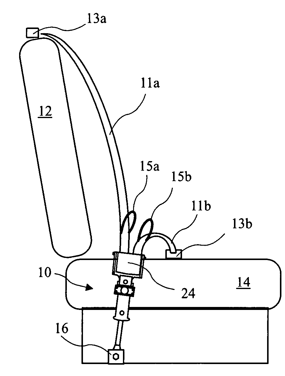
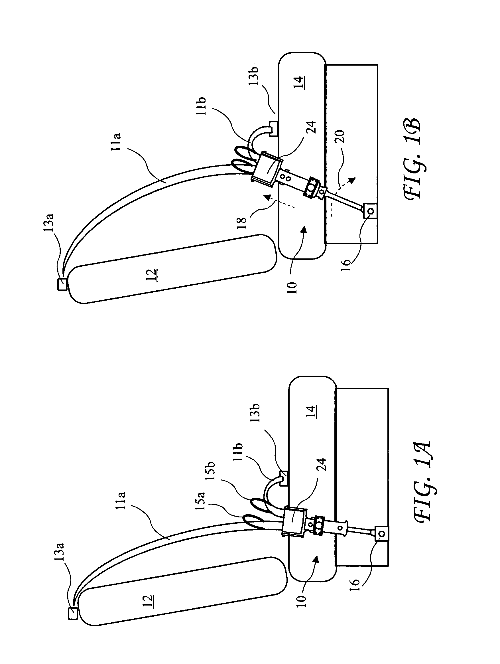
[0039]A restraint system according to the present invention is shown adjusted to a first position for a small soldier without gear in FIG. 1A, and adjusted to a second position for a large soldier wearing substantial gear in FIG. 1B. The restraint system may further be adjusted to intermediate positions. Soldiers often wear (or carry) gear such as backpacks, body armor, guns, canteens radios and maps. Soldiers may further wear arctic gear or chemical gear, both of which may substantially add to the overall girth of the soldier. Soldiers wearing such gear may be hampered by thick multiple layer gloves and experience constrained body movements. The ...


PUM


Abstract

A combat vehicle restraint system accommodates a wide range of soldiers, both with and without battle, arctic, or chemical gear. The restraint system includes lengthened belts and an adjustable buckle position. The belts include loops for locating and grasping the belts, and separate lap and shoulder belts with small narrowing ends to prevent catching on gear. The belts are extendable from Inertial reels which are calibrated for off-road operation. The buckle engages each belt separately and includes a single action release. The buckle position is easily adjusted using an oversized knob so that a soldier may easily find and adjust buckle length in the dark, wearing heavy gloves, or with muddy slippery fingers. The latch / unlatch mechanism and associated hardware is an open frame type to reduce or eliminate affects of mud, dust, water or other contaminants on operation.

Description

BACKGROUND OF THE INVENTION[0001]The present invention relates to occupant restraint systems for vehicles used in combat zones and in particular to a seat harness providing ease of use and improved occupant protection.[0002]From 1985 to the present, a standard automotive style 3-point restraint system (i.e., harness) with a push button release buckle has been supplied in military Humvee vehicles. This harness has resulted in numerous safety problems because it was not designed for the unique requirements of soldiers in combat situations[0003]A recent solicitation from the government to improve occupant safety and usage included many requirements. One of the top requirements was to fit a wide range of soldiers both with and without battle gear. Battle gear is equipment worn by the soldier when in hostile situations. The gear includes personal armor, a vest for carrying equipment, a backpack, a water container (Camel Back) and numerous other types of additional equipment. A result of ...

Claims


Application Information

Patent Timeline
Patent Type & Authority Patents(United States)
IPC IPC(8): B60R22/20B60R22/34
CPCB60R22/30B60R22/12Y10T24/45084B60R2022/1806
Inventor VAN DRUFF, CHARLES E.CHURILLA, JOHNKAWABATA, ERIC
Owner COBHAM MISSION SYST DAVENPORT LSS INC
Why Eureka
Try Eureka