Method and device for placing an endotracheal tube

a technology of endotracheal tube and endotracheal tube, which is applied in the field of medical devices, can solve the problems of increasing the risk of ett getting caught on the laryngeal tissue, increasing the likelihood of laryngeal injury, and difficulty in passing the ett into the airway of the patient, so as to improve the patient's safety.

Inactive Publication Date: 2008-03-20
NELSON LINDSEY A +1
View PDF36 Cites 19 Cited by
  • Summary
  • Abstract
  • Description
  • Claims
  • Application Information

AI Technical Summary

Benefits of technology

[0007]The above mentioned difficulties are overcome with the illustrative method and device for placing an ETT in a patient. The device includes an elongated tubular structure having an airway therein, which is insertable into the passageway of the ETT to allow rescue oxygenation and ventilation during placement of the ETT. Furthermore, the device includes a stylet that is adapted to slide smoothly over the tubular structure, such as by use of an activated lubricant and preferably the device includes means for which the stylet can slide on maintaining its orientation in relation to the tubular structure. Preferably the stylet has a tapered section with an expandable portion that gradually increases in diameter as it goes from distal to proximal on the stylet. When slid over the tubular structure the tapered portion of the stylet gently opens up the laryngeal tissue, preventing the ETT from catching on the tissue. The ETT then smoothly passes through the glottic opening and into the trachea without difficulty. As a result, this device for exchanging an established ETT and for primary placement of an ETT is a significant advancement in overcoming major obstacles and improving patient safety while placing an ETT.

Problems solved by technology

Often times this gap creates difficulty for passing the ETT into the patients airway as the ETT “catches” or gets “hung up” on the laryngeal inlet because of the existing space between the guide and the ETT.
Therefore, not only is the risk of the ETT getting caught on the laryngeal tissue increased but the tissue is now exposed to the hard bevelled edge of the plastic ETT increasing the likelihood of laryngeal injury (haematoma, vocal cord dysfunction, pain, arytenoid dislocation).
Because the tissue around an existing ETT often becomes edematous and engorged the laryngeal inlet may collapse down on the obturator once the existing ETT is removed.
In this event excessive force and rotation is usually required to overcome the “hang-up” of the ETT on the laryngeal anatomy.
If these measures are unsuccessful the operator may need to downsize the ETT (i.e. decrease the diameter difference between the oburator and the ETT) to facilitate replacement.
When this difficulty is encountered the patient is not able to be oxygenated or ventilated.
In addition, the insertion of the replacement ETT with increased force tends to cause trauma or bleeding to the airway increasing the complications associated with ETT exchange.
Further, obturators have been designed with hollow lumens to allow the passage of oxygen into the patient's lungs while difficulty passing the ETT is being encountered.
However, this is only a brief temporizing measure as the size of the lumens are extremely small and still do not circumvent the problem associated with the “hang-up” of the ETT.
Because the patient is often times awake this is very disturbing as patients may become extremely combative and fearful increasing the degree of difficulty for placing the ETT and also increasing the risk of injury to both the laryngeal tissue and cervical spine (if immobility required).

Method used


Image

  • Method and device for placing an endotracheal tube
  • Method and device for placing an endotracheal tube
  • Method and device for placing an endotracheal tube

Examples


Embodiment Construction

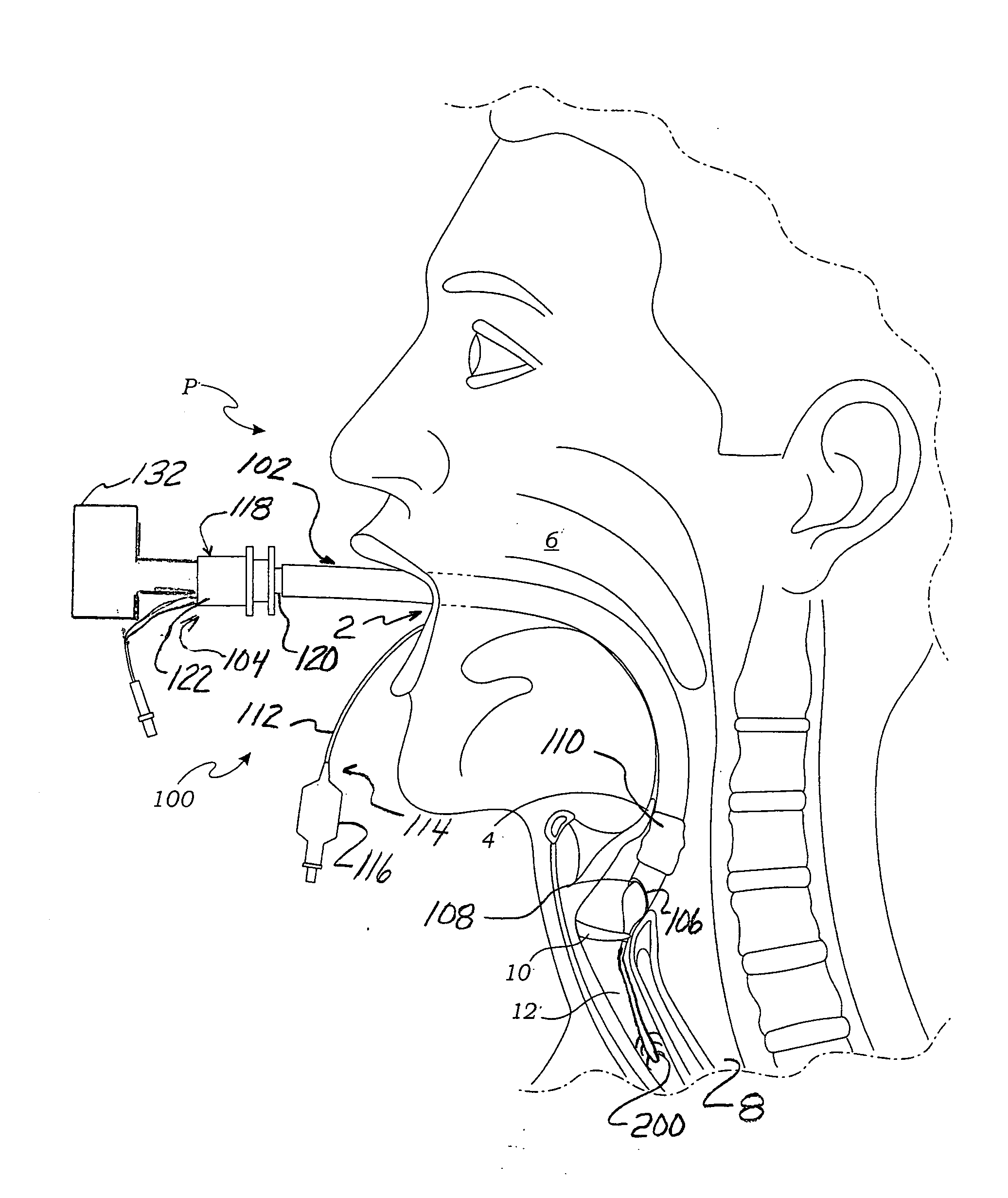
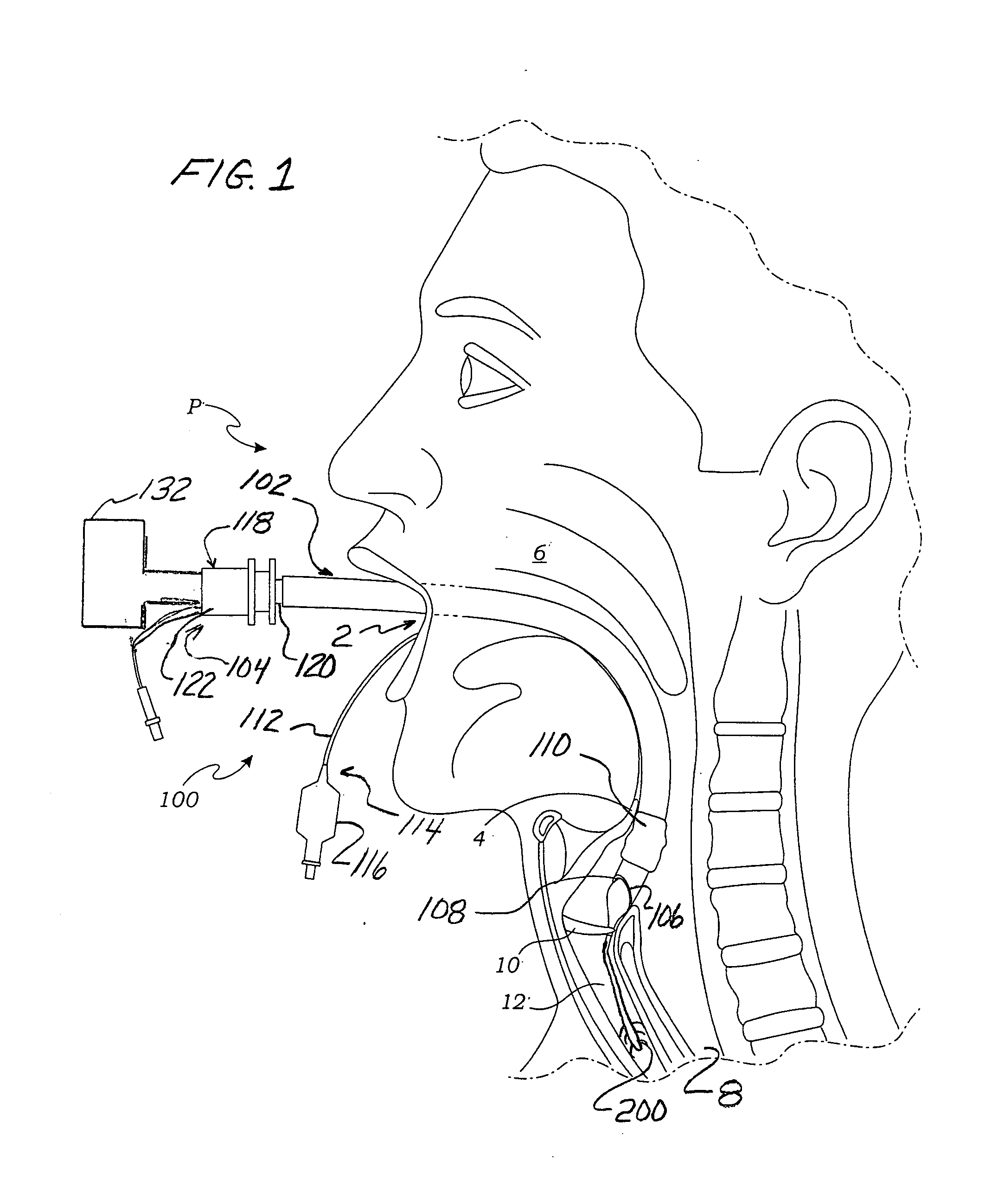
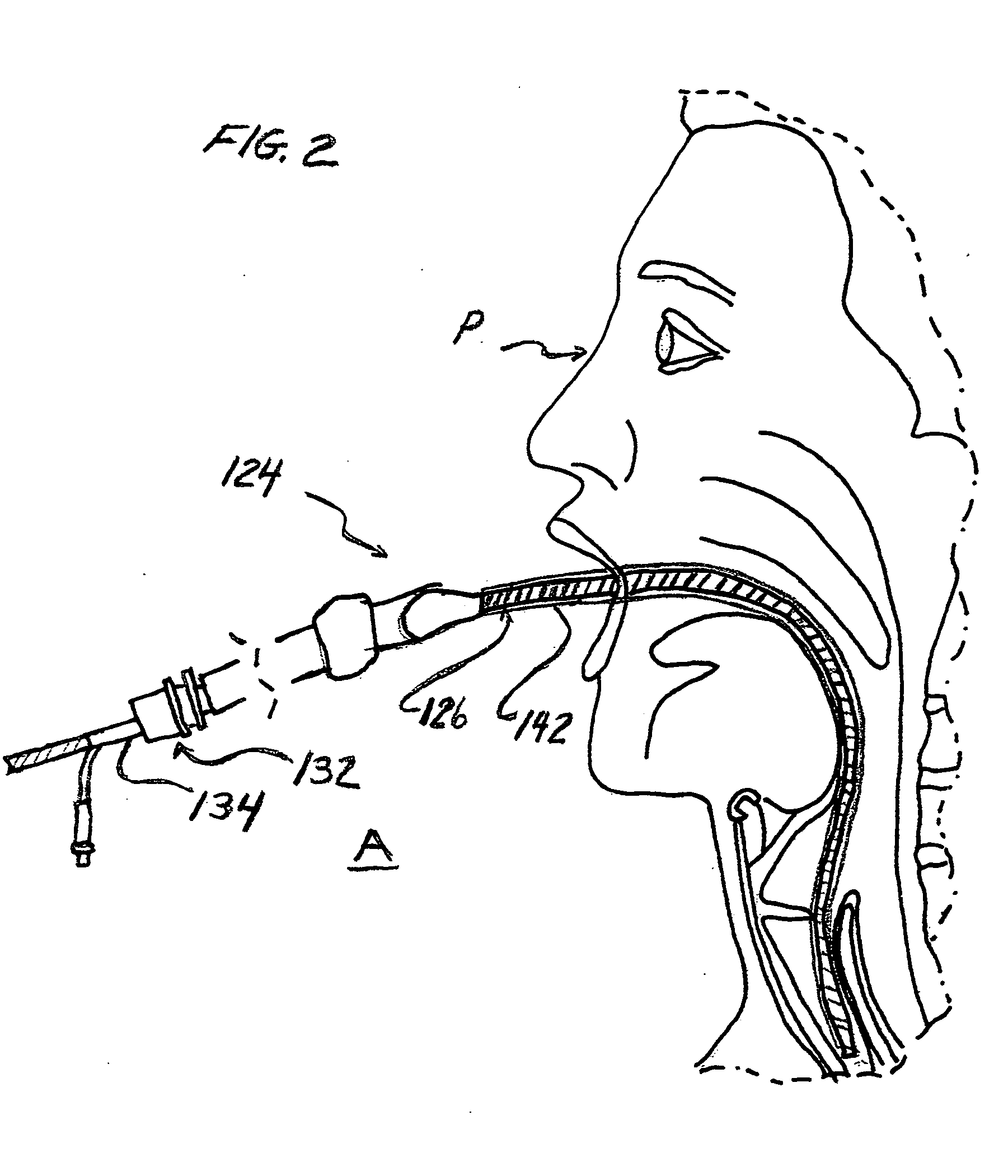
[0019]The present invention relates to a device and method of performing endotracheal intubation and more particularly to a new and novel apparatus and method for placing an ETT or for replacing an ETT that has been placed in a patient. In describing the preferred embodiments of the invention illustrated in the drawings, specific terminology will be resorted to for the sake of clarity. However, the invention is not intended to be limited to the specific terms so selected, and it is to be understood that each specific term includes all technical equivalents that operate in a similar manner to accomplish a similar purpose.

[0020]For purposes of the description of the present invention, the terms “forward” and “forwardly” are intended to refer to the direction towards the patient receiving the intubation device, whereas the terms “rear” and “rearwardly” are intended to refer to the direction away from the patient receiving the intubation device. The term “proximal” refers to a position ...


PUM


Abstract

Device and method for inserting an endotracheal tube or for replacing an endotracheal tube that already exists in the trachea with a new endotracheal tube. The device comprises a tubular structure effective for providing ventilation to the patient during replacement of the endotracheal tube. A stylet is provided having a taper section that gradually increases in diameter from the distal end thereby eliminating the difference in diameters between the tubular structure and the endotracheal tube and for facilitating entry of the new endotracheal tube into the trachea of the patient.

Description

CROSS-REFERENCE TO RELATED APPLICATION[0001]This application claims benefit of U.S. Provisional Application Ser. No. 60 / 844,429, filed Sep. 14, 2006, which is directed to a method and apparatus for replacing a placed endotracheal tube.TECHNICAL FIELD[0002]This invention relates to medical devices and more particularly to a method and apparatus for placing an endotracheal tube in a patient and more particularly, to a method and apparatus for placing an endotracheal tube in a patient or for exchanging an existing inserted endotracheal tube (ETT) and placing a new ETT by another conduit such as a fiberoptic bronchoscope.BACKGROUND OF THE INVENTION[0003]The placement of an ETT into a patient often requires the assistance of a guide. In situations where the ETT requires exchange, a tubular obturator is typically used as a guide; the obturator is passed down the existing inserted ETT, the ETT is then removed and a new ETT is passed over the obturator in attempt to guide its placement into...

Claims


Application Information

Patent Timeline
Patent Type & Authority Applications(United States)
IPC IPC(8): A61M16/00
CPCA61B1/2676A61M16/0488A61M16/04A61M16/0429
Inventor NELSON, LINDSEY A.LISCO, STEVEN J.
Owner NELSON LINDSEY A
Why Eureka
Try Eureka