
Rotating inertial pin blank stops for pressware die sets

Inactive Publication Date: 2007-01-30
GPCP IP HLDG LLC
View PDF18 Cites 19 Cited by
  • Summary
  • Abstract
  • Description
  • Claims
  • Application Information

AI Technical Summary

Benefits of technology

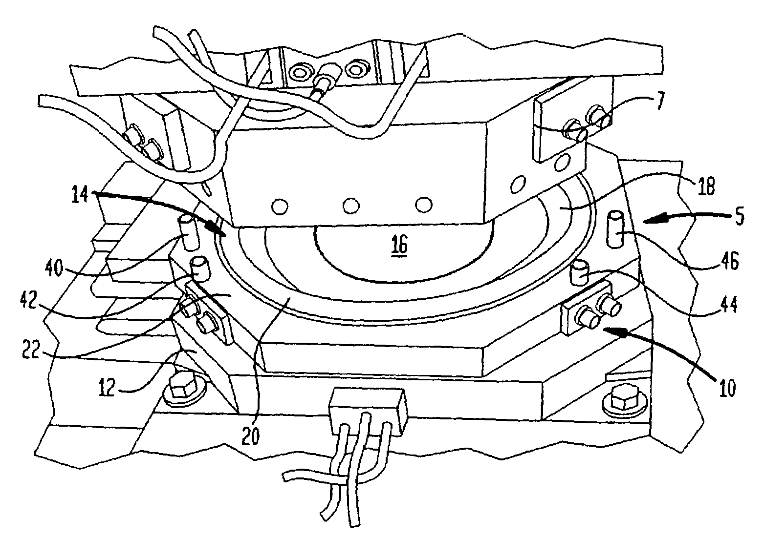
[0018]Blanks fed by gravity into the pressware sets that hit against fixed stops whether angular stops or fixed non-rotating pin stops, can rebound / “bounce back” from the stops or contact only one stop and stop prematurely resulting in off center formation of the pressware product. The rotating pin stops in accordance with the present invention absorb the kinetic energy of the blanks and reduce or eliminate blank “bounce”. The rotating pin stops also allow the blank to roll or move to an on center position more quickly allowing consistent product formation at higher speeds. The likelihood of contacting one set of rotating pin stops / prematurely stopping is reduced or limited since the blanks will tend to roll or move into an on center position until all rotating pin stops have been contacted. Off center forming of the product can result in lower product strength, improper print design, and product shape esthetics and a non-uniformed product stack. Pressware forming speeds can be limited by blanks that “bounce” off the fixed stops or are quickly positioned on center in the forming die set.
[0019]The preferred blank stop technique described in detail below, involves the use of four rotating pin blank stops. Two sets of pins located towards the front of the die set absorb the blanks kinetic energy by spinning / rotating and quickly guiding the blank by rolling or moving it until it contacts all four pins. The two pins of each set which are located more towards the front and center are shorter in some embodiments so that the formed product can be ejected over the top of them without interference. The rotating pin stops may have a flat or angled bottom which contacts against the die set or draw ring. The rotating pin stops may be attached with shoulder bolt screws or in any other manner that will not restrict the pin rotation. Preferably, shoulder bolts are inserted into the pin stops to hide the screw head and prevent blanks from catching on them. The counter bore depth and diameter are sized to allow clearance around the shoulder bolt for free pin rotation. The pin diameters are chosen to center the blank in the forming die set. Differing pin diameters can be produced and installed if necessary to compensate for blank curl. Optionally, the two sets of rotating pins can be mounted to independent components which can be radially shimmed or positioned inwardly or outwardly with a constant pin diameter to center the blank in the forming die set.

Problems solved by technology

Blanks fed by gravity into the pressware sets that hit against fixed stops whether angular stops or fixed non-rotating pin stops, can rebound / “bounce back” from the stops or contact only one stop and stop prematurely resulting in off center formation of the pressware product.
Off center forming of the product can result in lower product strength, improper print design, and product shape esthetics and a non-uniformed product stack.

Method used


Image

  • Rotating inertial pin blank stops for pressware die sets
  • Rotating inertial pin blank stops for pressware die sets
  • Rotating inertial pin blank stops for pressware die sets

Examples


Embodiment Construction

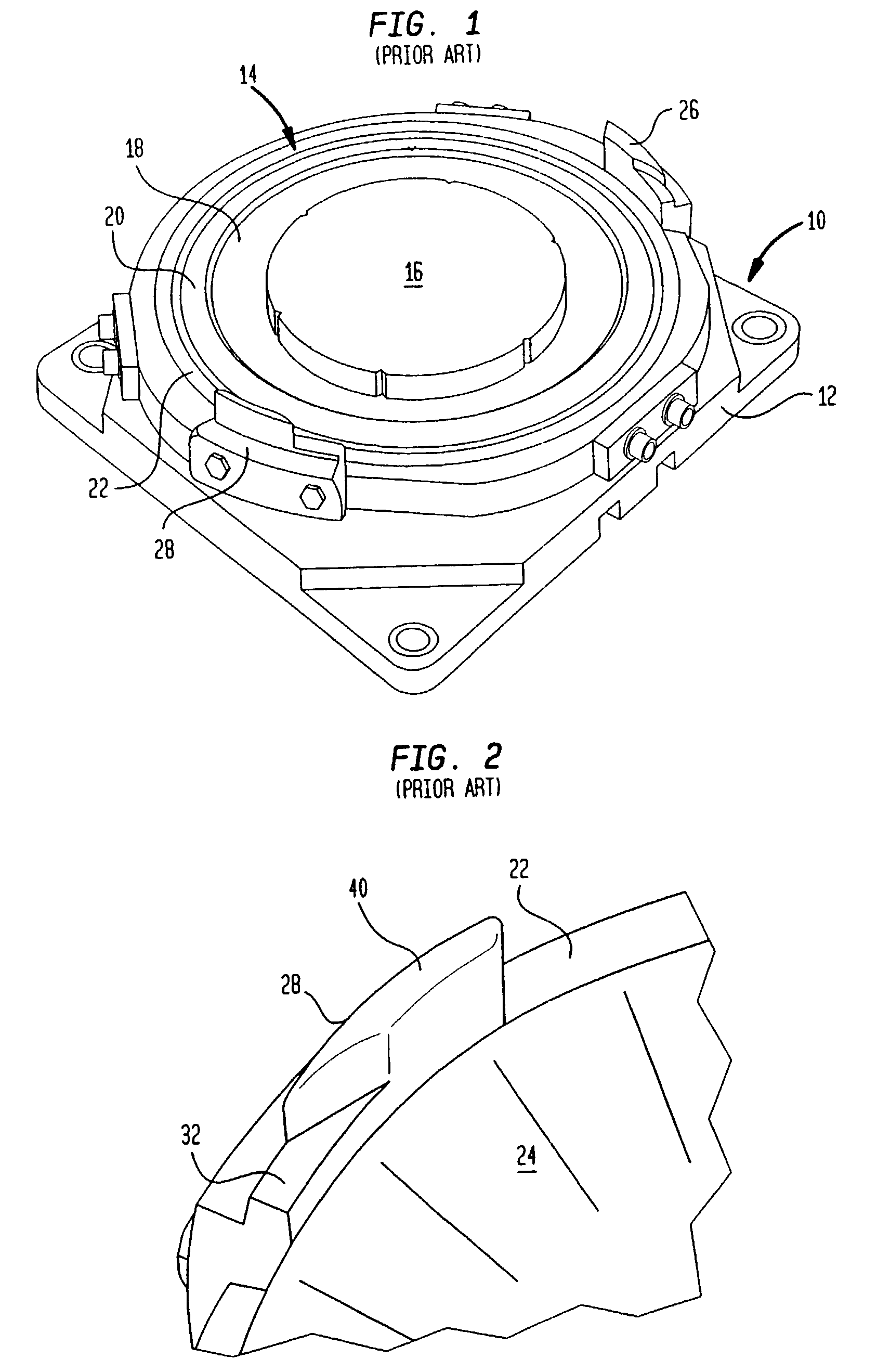
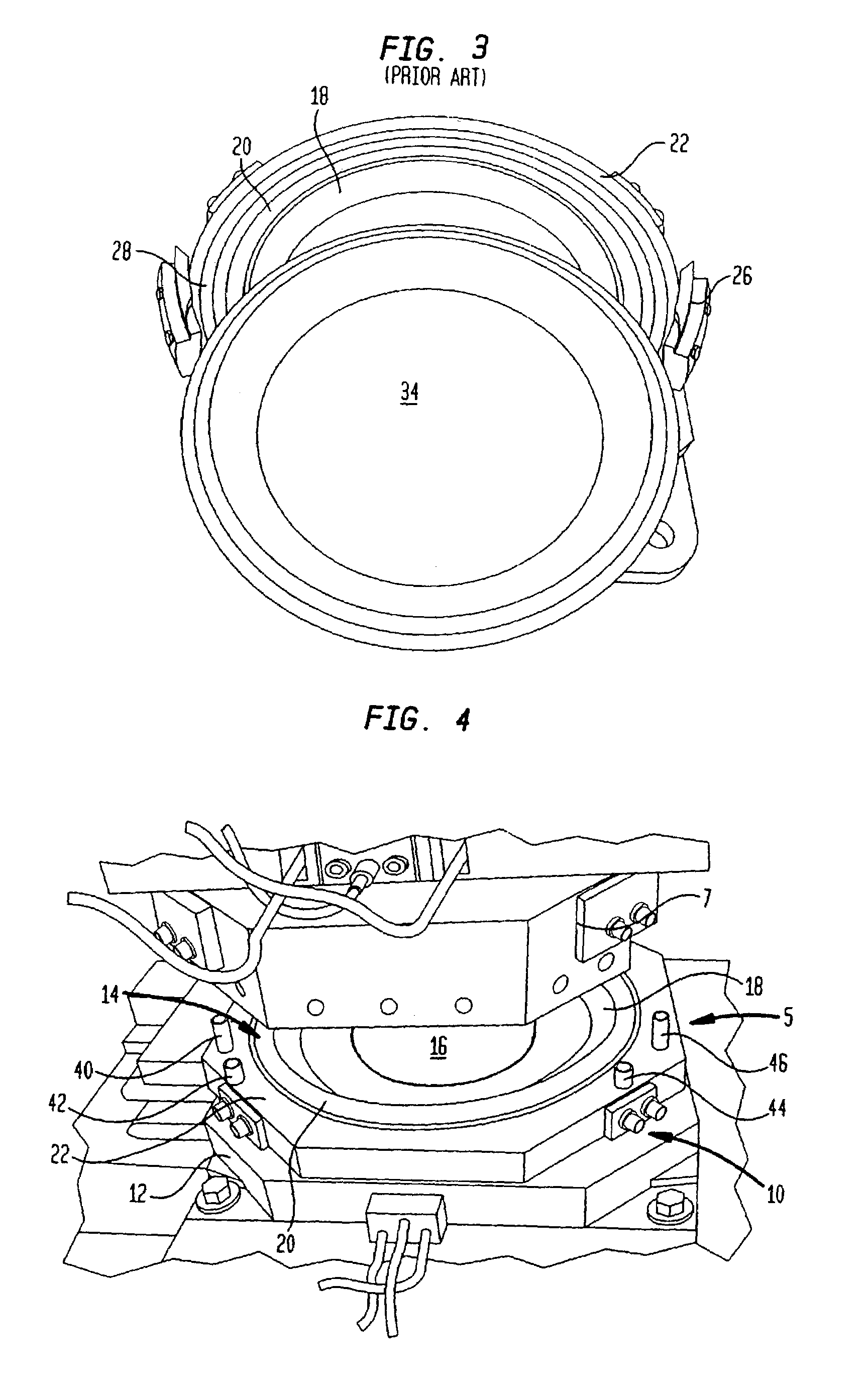
[0033]The present invention is described in detail below with reference to the various figures. Modifications to particular embodiments will be readily apparent to those of skill in the art and the particular embodiments illustrated are in no way intended to limit the invention which is defined in the appended claims. There is shown in FIGS. 1 through 3 a conventional lower die press assembly for making pressed paper products.

[0034]Assembly 10 includes a mounting plate 12 which supports a lower segmented die 14. Segmented die 14 includes a full area knock-out ring 16 which is shown extended as it would be into the die cavity. Die 14 is also provided with a side wall forming section 18, a rim forming portion 20 and a draw ring 22. As will be appreciated by one who is skilled in the art, assembly 10 is typically mounted below a punch die in an inclined manner. In use container blanks such as paper blank 24 (FIG. 2) are gravity fed to lower die 14. Paper blanks, such as blank 24, may b...


PUM

PropertyMeasurementUnit
Percent by massaaaaaaaaaa
Diameteraaaaaaaaaa

Abstract

In an apparatus for manufacturing pressware containers from container blanks there is provided a plurality of inertial blank stop pins disposed so as to position a container blank prior to press forming. The stop pins are rotatable in order to absorb the kinetic energy of the container blanks as they are fed to the apparatus and eliminate blank bounce. In a further aspect of the invention there is provided a method of forming plates utilizing the improved apparatus including the inertial blank stop pins.

Description

CROSS-REFERENCE TO RELATED APPLICATIONS[0001]This patent application is a divisional patent application of U.S. Ser. No. 09 / 653,577, filed Aug. 31, 2000, now U.S. Pat. No. 6,592,357, which application was based on U.S. Provisional Application Ser. No. 60 / 153,168, filed Sep. 9, 1999. The priorities of the foregoing applications are hereby claimed.TECHNICAL FIELD[0002]The present invention relates generally to the manufacture of food serving disposable pressware containers from container blanks and more particularly to blank stops disposed on the lower die half of an inclined die set adapted to position a container blank for pressing into a plate, bowl, tray or the like.BACKGROUND[0003]Disposable pressware containers made from paperboard and so forth, such as plates, trays, bowls and the like are well known in the art. Typically, such articles are manufactured on an inclined die set having upper and lower halves. Illustrative in this regard is U.S. Pat. No. 5,249,946 to Marx assigned ...

Claims


Application Information

Patent Timeline
IPC IPC(8): B29C31/00B29C43/02B29C31/08B29C43/36B29C59/00B25B11/00B31B50/28B31B50/59
CPCB31B43/00B29C33/10B29C43/361B29C2043/3615B31B2201/223B29L2031/712B29K2711/123B31B70/00B31B2160/10B31B50/592
Inventor JOHNS, ALBERT D.LITTLEJOHN, MARK B.SOFRONIE, MIRCEA T.
Owner GPCP IP HLDG LLC
Learn More