Tripod type constant velocity joint

Active Publication Date: 2006-11-21
NTN CORP
View PDF12 Cites 8 Cited by
  • Summary
  • Abstract
  • Description
  • Claims
  • Application Information

AI Technical Summary

Benefits of technology

[0010]According to an embodiment of the invention, a tripod type constant velocity joint comprises a hollow cylindrical housing fixed to the end of a first rotary shaft and formed with axially extending recessed grooves opened at one axial end and located at circumferentially trisectional positions on the inner peripheral surface, a tripod consisting of a boss fixed to the end of a second rotary shaft, and end-spherical trunnion journals radially projecting from circumferentially trisectional positions on the boss, roller assemblies each consisting of an inner roller swingably fitted at the inner peripheral surface thereof on the spherical outer peripheral surface of the trunnion journal, and an outer roller supported for rotation and axial movement on the outer peripheral surface of the inner roller through needle rollers, wherein the outer rollers are received in the recessed grooves in the housing and are rollable axially of the housing, each recessed groove consists of guide surfaces contacting the outer peripheral surface of the outer roller and subjected to loads, and guide shoulder surfaces for guiding the outer roller axially of the housing, and only the side of the outer diameter of said boss associated with the end of the second rotary shaft is heavily chamfered. This embodiment is arranged so that during assemblage by tilting the roller until the projected shorter radius of the trunnion journal (in a direction at right angles with the load-subjected side) is reduced to not more than its inner diameter at its end on the inner roller fitting side, the roller does not interfere with the boss of the tripod (journal underhead). Since torque transmission between the tripod and the second rotary shaft is effected mostly by the second rotary shaft non-end side in the boss, heavily chamfering the boss at the second rotary shaft end does not lead to a lowering in the boss strength. Mounting this tripod type constant velocity joint on a vehicle makes it possible to reduce the vibration of the vehicle and to ensure coexistence of high strength and durability.

Problems solved by technology

Adopting such arrangement makes it difficult for the outer roller to be detached from the inner roller in the state of the tripod kit (a unit consisting of the tripod and the roller assembly), making handling easy.
Adopting such arrangement makes it difficult for the outer roller to be detached from the inner roller in the state of the tripod kit, making handling easy.

Method used


Image

  • Tripod type constant velocity joint
  • Tripod type constant velocity joint
  • Tripod type constant velocity joint

Examples


Embodiment Construction

[0038]An embodiment of the invention will now be described with reference to the drawings.

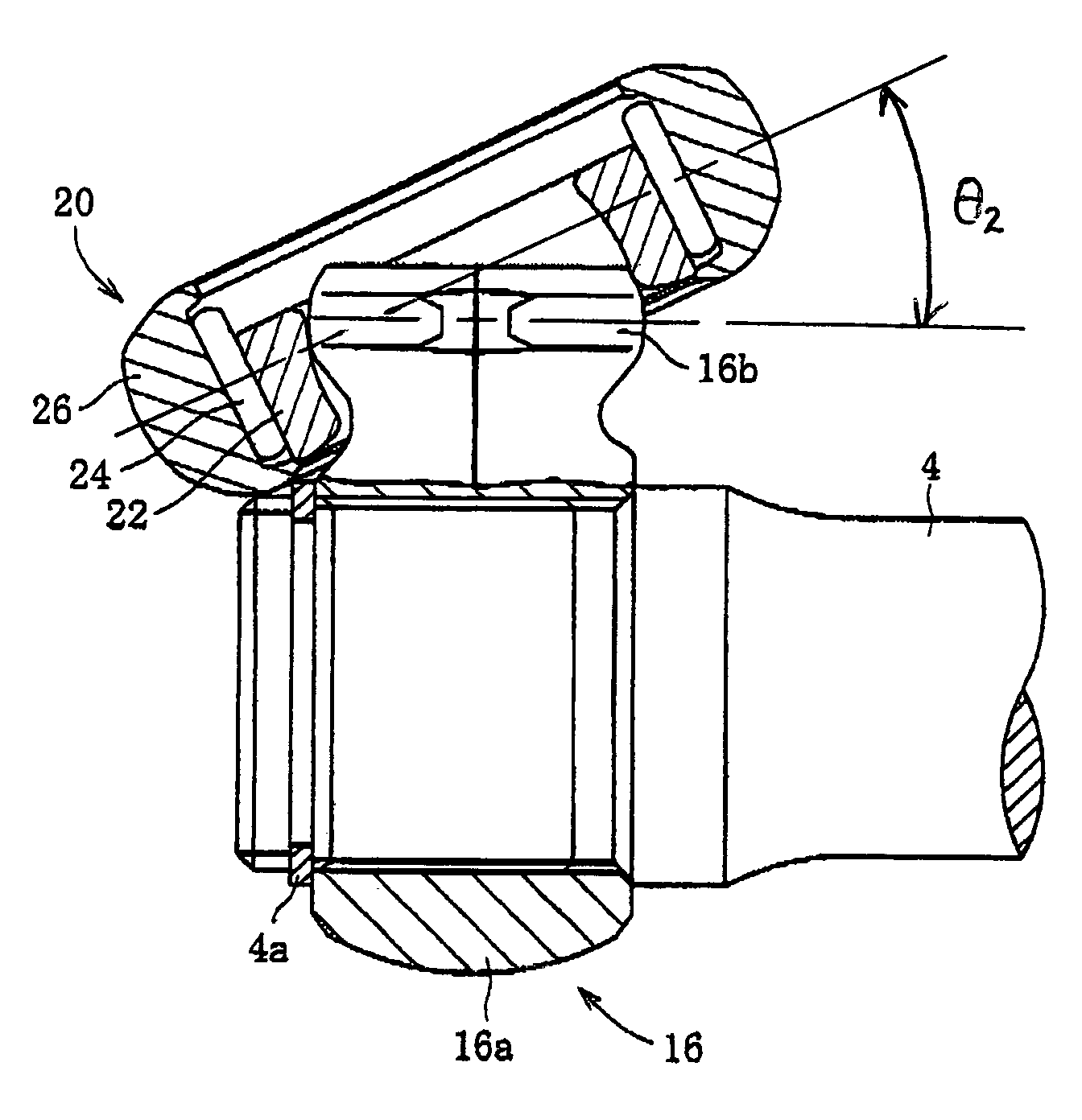
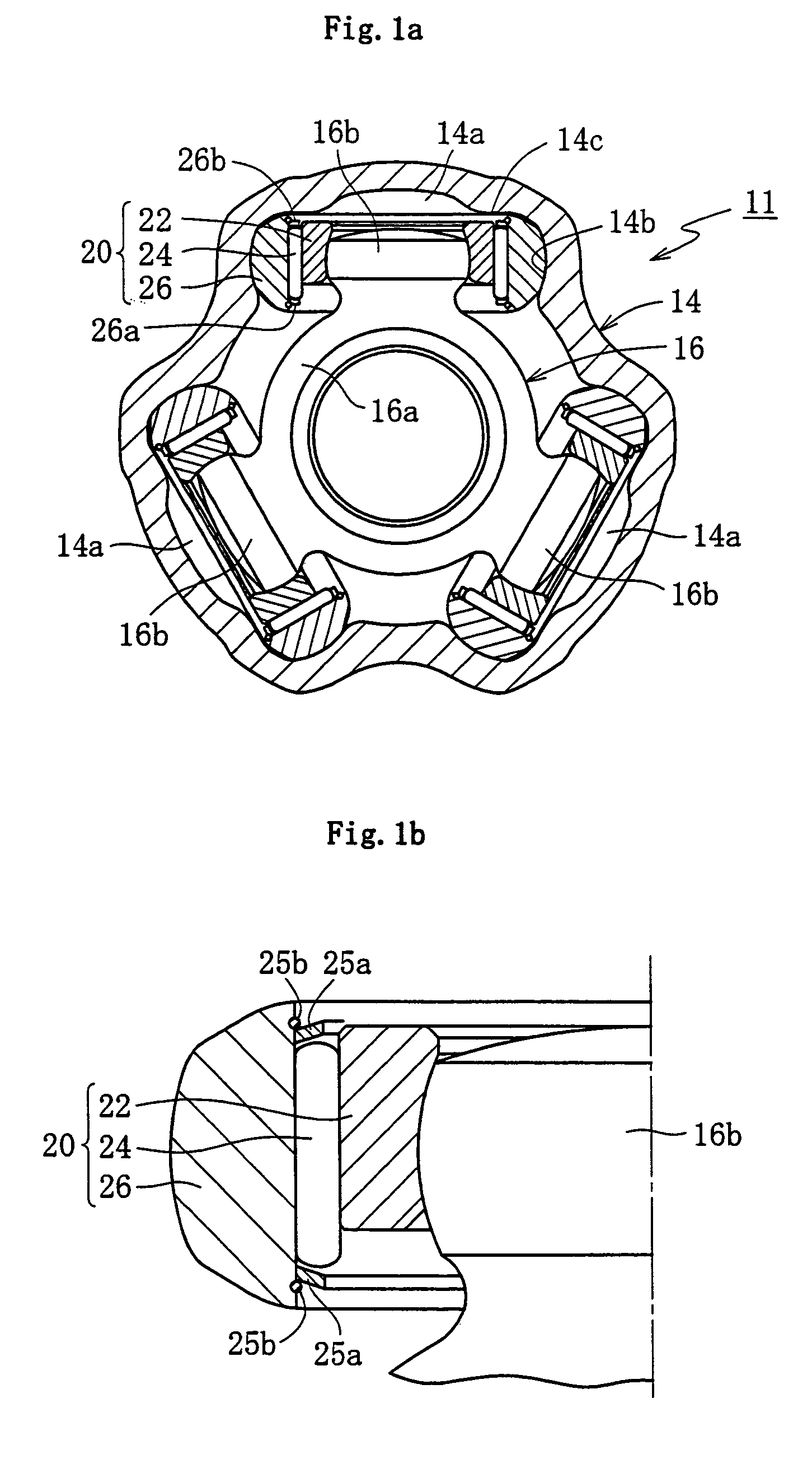
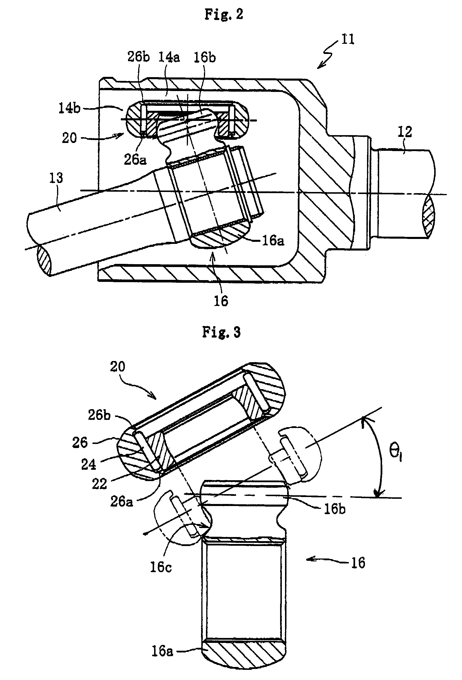
[0039]First, referring to FIGS. 1a, 1b and 2, a tripod type constant velocity joint 11 is no different from the one shown in FIGS. 15 and 16 described previously, as far as the basic arrangement is concerned, comprising a hollow cylindrical housing 14 fixed to the end of a first rotary shaft 12, such as a driving shaft, and a tripod 16 fixed to the end of a second rotary shaft 13, such as the rotary shaft on the wheel side.

[0040]The housing 14, herein, is formed integrally with the first rotary shaft 12, and has axially extending recessed grooves 14a at circumferentially trisectional positions on the inner peripheral surface. Each recessed groove 14a is recessed to extend radially outward from the inner peripheral surface of the housing 14, and is composed of a pair of circumferentially opposed guide surfaces 14b and a bottom surface positioned on the radially outside of the housing and connect...


PUM


Abstract

Tripod type constant velocity joint has a hollow cylindrical housing fixed to the end of a first shaft and has axially extending recessed grooves opened at one axial end and located at circumferentially trisectional positions on an inner peripheral surface. A tripod has a boss fixed to the end of a second shaft with end-spherical trunnion journals radially projecting from circumferentially trisectional positions on the boss. Roller assemblies each have an inner roller fitted on the spherical surface of the trunnion journal and an outer roller supported for rotation and axial movement on the inner roller. The outer rollers are received in the recessed grooves and rollable axially of the housing. Each recessed groove has guide surfaces contacting the outer surface of the outer roller. Guide shoulder surfaces guide the outer roller axially of the housing. A relief is locally formed along a forged parting line of the trunnion journal.

Description

BACKGROUND ART[0001]The present invention relates to a tripod type constant velocity joint used for transmission of a rotary force between rotary shafts incorporated in the driving system, for example, of an automobile and non-linearly existing therein.[0002]Tripod type constant velocity joints are in wide use as a kind of constant velocity joint to be incorporated in the driving systems of automobiles. For example, Japanese Patent Laid-Open Publication Sho 62-233522 discloses a tripod type constant velocity joint 1 as shown in FIGS. 15 and 16. This tripod type constant velocity joint 1 comprises a hollow cylindrical housing 3 fixed to the end of a first rotary shaft 2, such as a driving shaft, and a tripod 5 fixed to the end of a second rotary shaft4, such as the rotary shaft on the wheel side.[0003]The inner peripheral surface of the housing 3 is formed, at circumferentially trisectional positions, with recessed grooves 6 extending axially of the housing 3. On the other hand, the ...

Claims


Application Information

Patent Timeline
IPC IPC(8): F16D3/205F16D3/20
CPCF16D3/2055Y10S464/905F16D2003/2026F16D3/20
Inventor ISHIJIMA, MINORUYAMAZAKI, KENTAIZUMINO, JUNICHI
Owner NTN CORP
Why Eureka
Try Eureka