Fuel cell system and its control method

Active Publication Date: 2009-10-29
TOYOTA JIDOSHA KK
View PDF4 Cites 5 Cited by
  • Summary
  • Abstract
  • Description
  • Claims
  • Application Information

AI Technical Summary

Benefits of technology

[0012]In general, as to a member such as a rubber member (e.g., a sealing member made of a rubber) or an electrolyte, the strength tends to lower as the temperature rises (see FIG. 8). In consideration of such properties, the supply quantities of various reactant gases are altered in accordance with the temperature of the fuel cell in the present invention. That is, the temperature of the fuel cell during starting is a parameter, and a fuel gas pressure value (a pressure range) capable of enhancing the starting performance of the fuel cell at the temperature is obtained using the parameter. In this case, when the pressure of the fuel gas piping system is increased so as to fall in the obtained pressure range, the fuel gas can quickly be supplied to a fuel pole to promote reaction and enhance the starting performance. In addition, since the temperature of the fuel cell is the parameter, a burden on the rubber member or the electrolyte in the temperature situation during the starting can effectively be suppressed.
[0013]Here, the gas supply quantity is preferably altered in accordance with the durable temperature characteristics of a passage member forming a gas passage of the reactant gas. As to the member forming the gas passage, for example, the sealing member made of the rubber or the resin, or a member such as the electrolyte whose strength lowers in an environment at the high temperature, the gas supply quantity (and the gas pressure value) can be adjusted in accordance with the durable temperature characteristics to effectively suppress the burden and suppress the deterio

Problems solved by technology

However, a reactant gas is supplied or gas pressure is increased, while durability against temperatures in sealing members of a fuel cell and various valves, an electrolyte and the like is not taken into account, so that deterioration of these se

Method used


Image

  • Fuel cell system and its control method
  • Fuel cell system and its control method
  • Fuel cell system and its control method

Examples


Example

[0027]A preferable embodiment of the present invention will hereinafter be described with reference to the drawings.

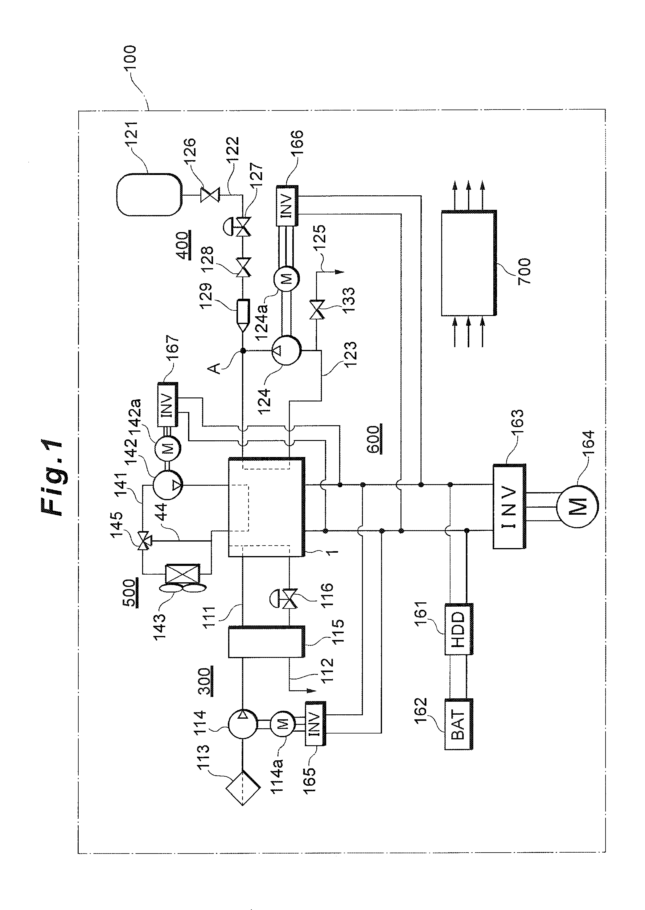
[0028]FIGS. 1 to 7 show the embodiment of a fuel cell system according to the present invention. A fuel cell system 100 according to the present invention includes gas piping systems 300, 400 for supplying a reactant gas to a fuel cell 1, and gas supply controllers 114, 116, 126 to 129 for altering the supply state of the reactant gas in response to a power generation request. A gas supply quantity is altered in accordance with the temperature of the fuel cell 1, whereby deterioration of a member made of a rubber, a resin or the like (e.g., a membrane-electrode assembly, a sealing member or the like) is suppressed while enhancing the starting performance of the fuel cell 1.

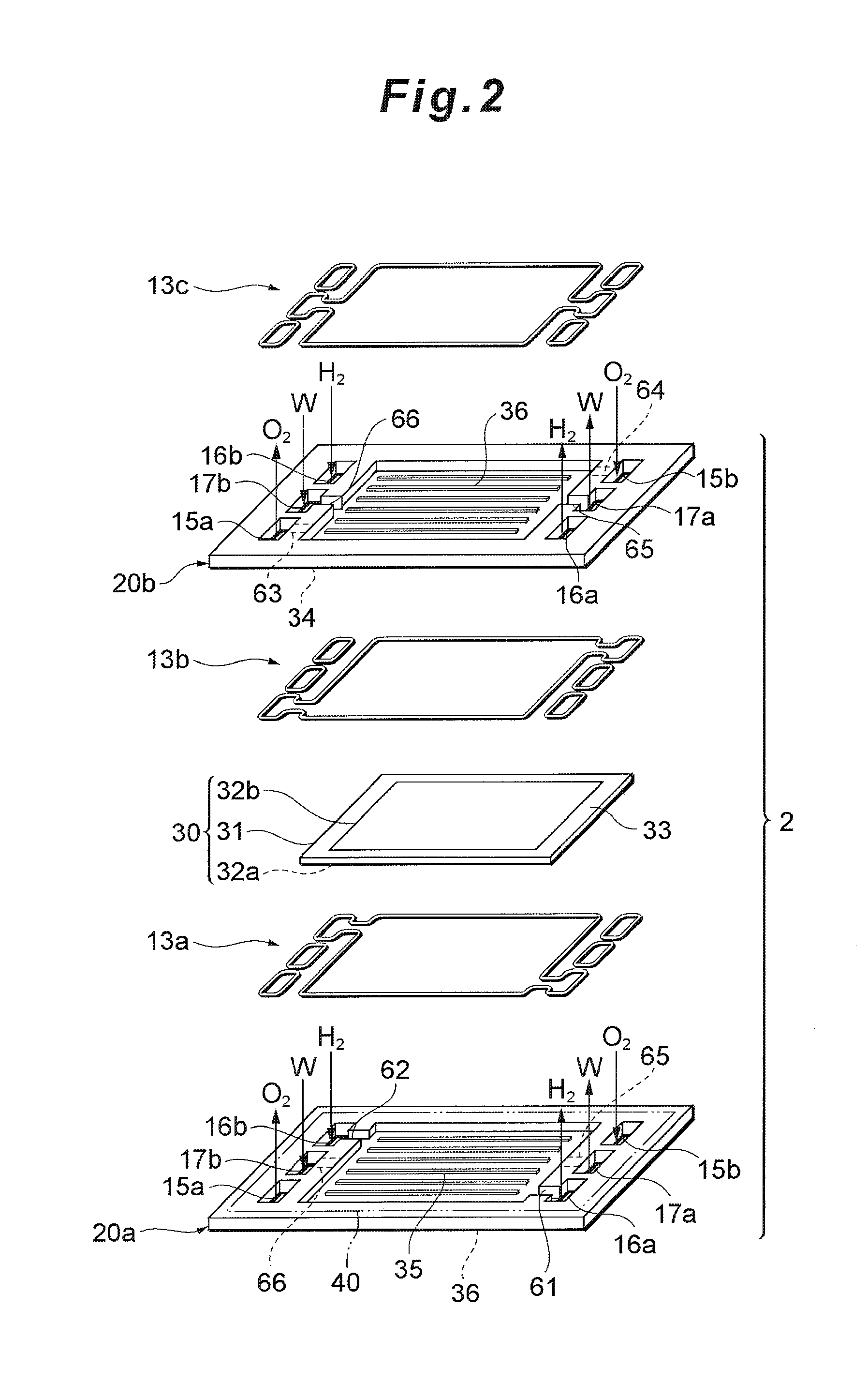
[0029]In the following description, first the whole constitution of the fuel cell system 100 and the constitution of a cell 2 constituting the fuel cell 1 will be described. Afterward, there will be ...


PUM


Abstract

Deterioration of an electrolyte and a sealing member is suppressed taking account of the durable temperature characteristics thereof, while enhancing the starting performance of a fuel cell. For this realization, in a system comprising a gas piping system for supplying a reactant gas to a fuel cell, and a gas supply controller for altering the supply state of the reactant gas in response to a power generation request, a gas supply quantity is altered in accordance with the temperature of the fuel cell. Preferably, the gas supply quantity is altered in accordance with the durable temperature characteristics of a passage member forming a gas passage of the reactant gas. Furthermore, the differential pressure of the gas supply state between the anode side and the cathode side of the fuel cell is preferably taken into account and the differential pressure between both poles is suppressed by altering the gas supply quantity on the cathode side as the case may be.

Description

BACKGROUND OF THE INVENTION[0001]1. Field of the Invention[0002]The present invention relates to a fuel cell system and its control method. More particularly, it relates to the improvement of a technology for supplying and discharging various reactant gases to and from a fuel cell.[0003]2. Description of Related Art[0004]In general, a fuel cell (e.g., a polymer electrolyte fuel cell) is constituted by laminating a plurality of cells, each of the cells including an electrolyte held between separators. Moreover, a fuel cell system is constituted of, in addition to such a fuel cell, a piping system for supplying and discharging a reactant gas (a fuel gas or an oxidizing gas) to and from the fuel cell, an electric power system which charges and discharges electric power, a control system which generally controls the whole system and the like.[0005]As the fuel cell system including such a fuel cell, for example, a system or the like is known in which a fuel gas (hydrogen gas) supply syst...

Claims


Application Information

Patent Timeline
IPC IPC(8): H01M8/04
CPCH01M8/04007H01M8/04104H01M8/04223H01M8/04328H01M8/04335Y02E60/50H01M8/0435H01M8/04365H01M8/04753H01M8/04783H01M8/04955H01M8/04343H01M8/04225H01M8/04302H01M8/2435
Inventor KATANO, KOJIYAMAGISHI, NORIOHOTTA, AKIHISA
Owner TOYOTA JIDOSHA KK
Why Eureka
Try Eureka