Electric Machine Comprising an Axial Spring-Loaded Element

Inactive Publication Date: 2007-11-08
ROBERT BOSCH GMBH
View PDF15 Cites 20 Cited by
  • Summary
  • Abstract
  • Description
  • Claims
  • Application Information

AI Technical Summary

Benefits of technology

[0002] The inventive electric machine and the inventive axial spring element having the characterizing features of the independent claims have the advantage that, due to the design of an outer ring that is connected with the inner ring of the spring element in a resilient manner, the spring element is capable of being securely fastened to a rotor component. As a result, the spring element can be installed together with the rotor component on the rotor shaft advantageously in one assembly step. Since the spring element is already fixedly connected to the rotor component when it is installed, the tolerance between the inner ring and the rotor shaft can be designed great enough to prevent the clamping ring from tilting when it is installed on the rotor shaft. In contrast to a spring element with radially projecting ends, the outer ring prevents the spring elements from catching on each other during shipment.
[0003] Advantageous refinements and improvements of the features indicated in the independent claims are made possible by the measures listed in the subclaims. By way of the elastic connection of the inner ring with the outer ring, the spring element can be fixedly fastened via the outer ring to a rotor component on one side, and an axial, resilient, annular contact surface can be provided on the other side for the bearing.
[0004] Since the spring element is fastened to the rotor component, the inner ring can be designed radially very narrow, so that it bears, on the bearing side, only against the inner part of the bearing that is connected with the armature shaft. As a result, friction between the inner part and the outer part of the bearing is prevented via its sealing disk, thereby increasing the efficiency of the electric machine.
[0005] It is particularly favorable to design the resilient segments between the inner ring and the outer ring to be spiral-shaped, so that the outer diameter of the spring element does not increase when an axial load is placed on it. The axial range of spring, however, is attained by rotating the outer ring relative to the inner ring, which reduces the amount of radial installation space required.
[0008] The outer ring, in particular with the circumferential outer wall, also creates further possibilities for fastening the spring element to the rotor component that are favorable in terms of process engineering. For example, the outer ring can engage in a rear section or in a detent element of the rotor component. The outer ring can also be designed together with the rotor component as a bayonet connection, or it can be fastened thereto via plastic material deformation of the rotor component. A separate assembly step for fastening the spring element is eliminated as a result.
[0008] The outer ring, in particular with the circumferential outer wall, also creates further possibilities for fastening the spring element to the rotor component that are favorable in terms of process engineering. For example, the outer ring can engage in a rear section or in a detent element of the rotor component. The outer ring can also be designed together with the rotor component as a bayonet connection, or it can be fastened thereto via plastic material deformation of the rotor component. A separate assembly step for fastening the spring element is eliminated as a result.
[0008] The outer ring, in particular with the circumferential outer wall, also creates further possibilities for fastening the spring element to the rotor component that are favorable in terms of process engineering. For example, the outer ring can engage in a rear section or in a detent element of the rotor component. The outer ring can also be designed together with the rotor component as a bayonet connection, or it can be fastened thereto via plastic material deformation of the rotor component. A separate assembly step for fastening the spring element is eliminated as a result.
[0009] Particularly favorably, the outer ring can be fastened directly to the end face of the armature lamitation core, which is easily installable on the rotor shaft. The rotor shaft is then supported in the pole pot of an electric motor via the roller bearing.
[0010] To compensate for material expansions of the electric machine, the roller bearing against which the axial spring element bears is designed as a floating bearing. The inner part of the ball bearing, e.g., that is fixed in position on the rotor shaft, is axially movable within certain limits relative to the outer part. By locating a floating bearing of this type on one end of the rotor shaft, the rotor shaft can be supported at another point in the housing an easily-manufactured fixed bearing, without resulting in overrigid support of the armature shaft.
[0011] The axial spring element according to the present invention is suitable for use to provide any type of support of a shaft with a non-rotatable component in a corresponding bearing receptacle. Since the dimensionally stable outer ring can be fixed relatively easily to the shaft components at least axially, the inner ring connected elastically therewith provides a bearing surface for an annular bearing component. As a result, particularly with a ball bearing designed as a floating bearing with a sliding fit—with play—of the inner part on the rotor shaft, the inner part can be braced axially, to minimize noise and wear. Due to the spiral-shaped, elastic connecting segments, the outer diameter of the spring element remains advantageously constant.

Problems solved by technology

With a design of this type, the plain washer must be installed in a separate method step; this can result in problems caused by the plain washer tilting, due to the guidance of the plain washer on the rotor shaft.

Method used


Image

  • Electric Machine Comprising an Axial Spring-Loaded Element
  • Electric Machine Comprising an Axial Spring-Loaded Element
  • Electric Machine Comprising an Axial Spring-Loaded Element

Examples


Embodiment Construction

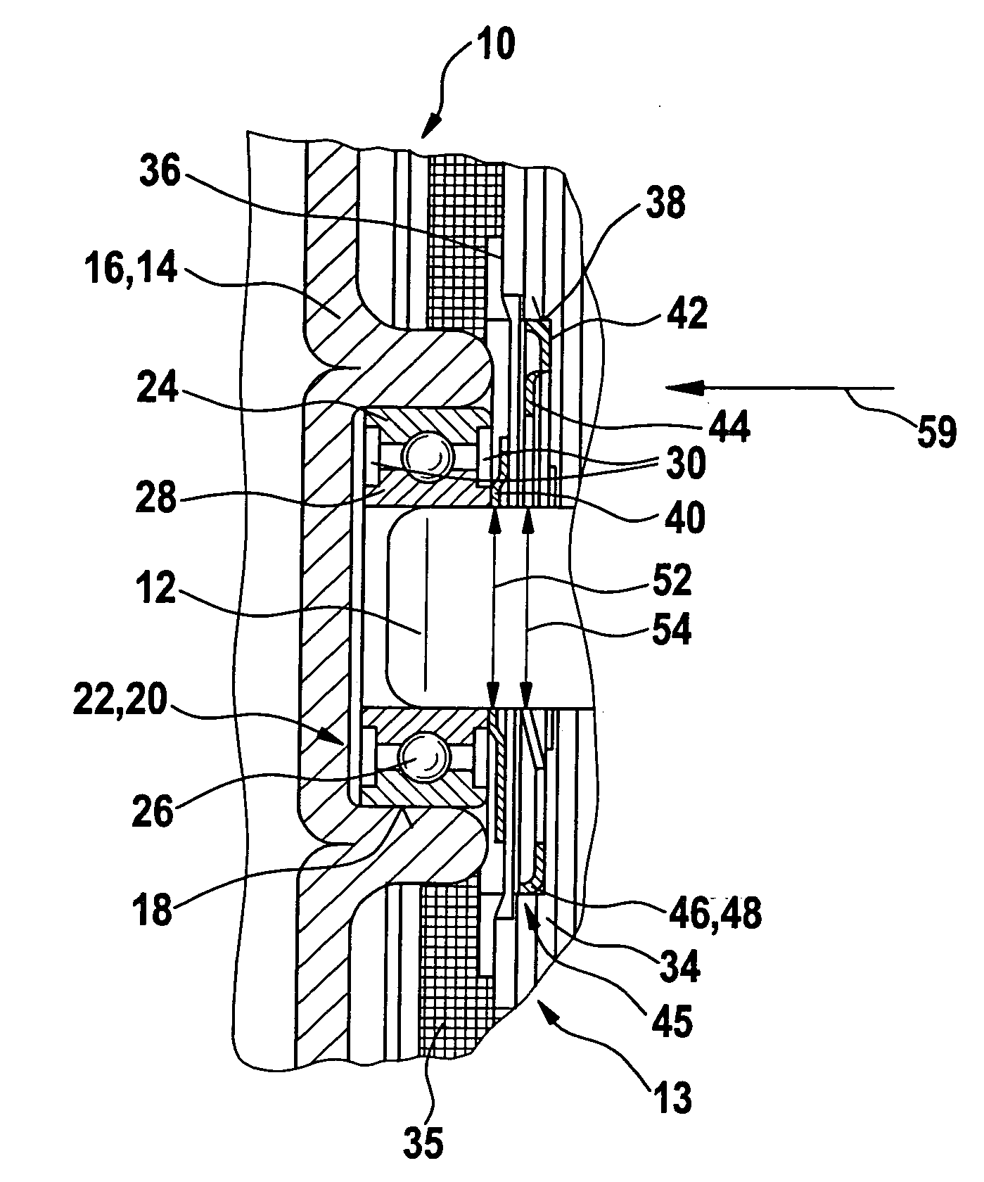
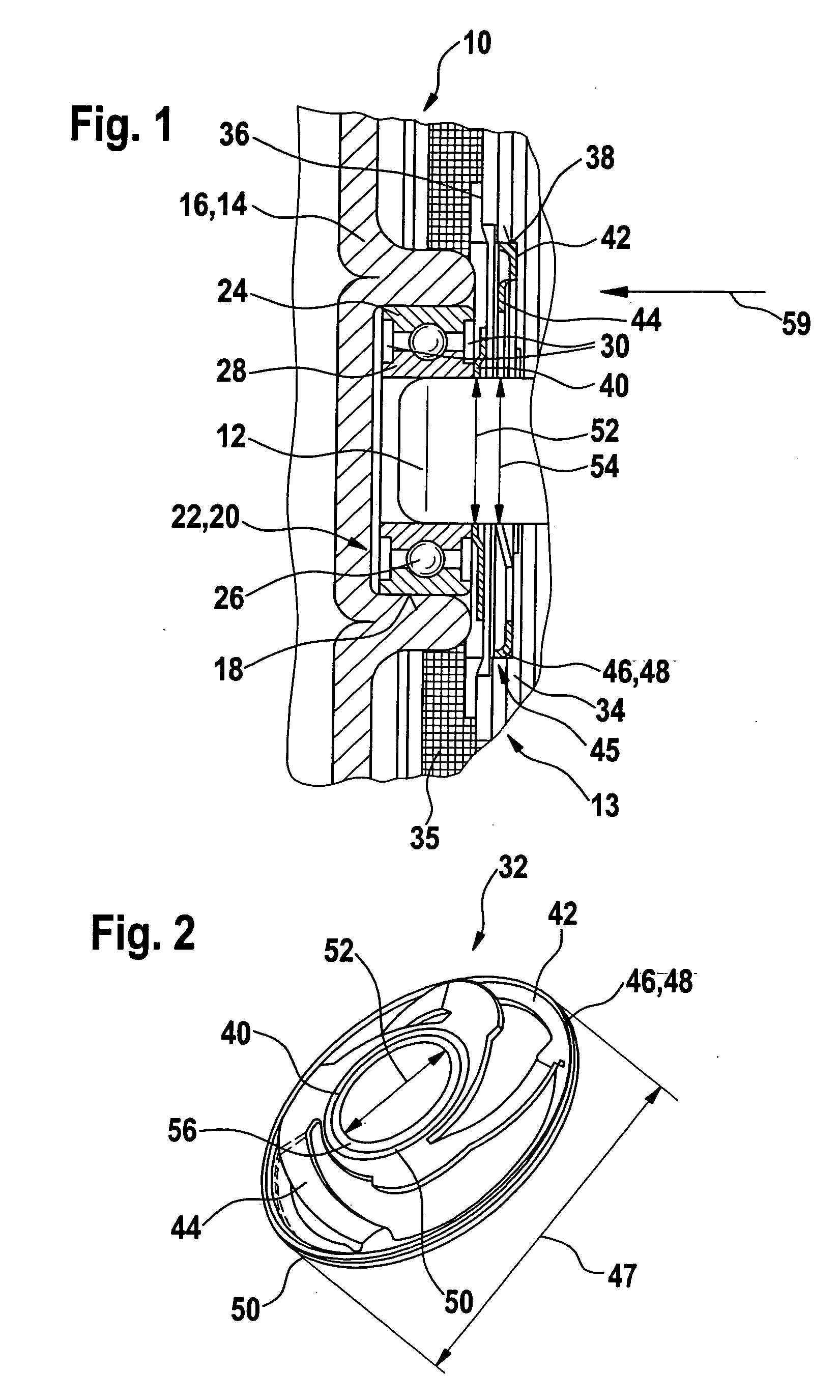
[0016]FIG. 1 shows an electric machine 10, with which a rotor 13 that includes a rotor shaft 12 is supported in a housing part 16 designed as a pole pot 14. Housing part 16 includes a bearing receptacle 18 in which a roller bearing 22 designed as a ball bearing 20 is located. Roller bearing 22 includes an outer part 24 that bears radially against bearing receptacle 18. Inner part 28 is rotatable relative to outer part 24 via rolling elements 26, rolling elements 26 being covered with sealing disks 30. Inner part 28 accommodates rotor shaft 12, and roller bearing 22 is designed as a floating bearing, which allows rotor shaft 12 to be displaced easily in an axial direction relative to housing part 16. An axial spring element 32 is located on rotor 13 to axially brace rotor shaft 12 relative to roller bearing 22. Axial spring element 32 bears against inner part 28 of roller bearing 22 on one side and, on the other, it bears against a rotor component 34 located non-rotatably on rotor sh...


PUM


Abstract

which is rotatably supported in a housing part (16) of a housing via a roller bearing (22, 20) An axial spring element (32) is located between the roller bearing (22, 20) and a rotor component (34) installed non-rotatably on the rotor shaft (12). The axial spring element (32) includes an inner ring (40) and an outer ring (42), which are interconnected in an axially resilient manner, and the outer ring (42) is axially connected to the rotor component (34).

Description

BACKGROUND INFORMATION [0001] The present invention relates to an electric machine with an axial spring element, and an axial spring element according to the generic part of the independent claims. An electric motor was made known in JP 2000 30 8305 A, with which a rotor is supported in a housing a ball bearing. A plain washer is located on the rotor shaft between the ball bearing and the rotor that supports the rotor axially against the ball bearing. The plain washer includes an annular part, on which radially projecting, resilient parts are integrally moulded, the resilient parts bearing against the rotor core in a resilient manner. With a design of this type, the plain washer must be installed in a separate method step; this can result in problems caused by the plain washer tilting, due to the guidance of the plain washer on the rotor shaft. ADVANTAGES OF THE INVENTION [0002] The inventive electric machine and the inventive axial spring element having the characterizing features ...

Claims


Application Information

Patent Timeline
Patent Type & Authority Applications(United States)
IPC IPC(8): H02K7/00
CPCF16C25/06H02K7/083H02K5/1732F16F1/326F16C25/083F16C2380/26
Inventor HEYDER, MARTIN
Owner ROBERT BOSCH GMBH
Why Eureka
Try Eureka