Electropneumatic horn system

a horn system and electro-pneumatic technology, applied in the direction of signalling system, electrical apparatus casing/cabinet/drawer, hydro-pneumatic audible signalling, etc., can solve the problems of inacceptable failure rate, relative structural weaknesses in the overall completed assembly, and easy failure of adhesive tap

Active Publication Date: 2010-09-28
WOLO MFG
View PDF57 Cites 7 Cited by
  • Summary
  • Abstract
  • Description
  • Claims
  • Application Information

AI Technical Summary

Benefits of technology

[0027]Another aspect of the present invention is to provide an electropneumatic horn system having increased resistance to vibration, thermal challenge, and chemical or environmental / weather related extremes.
[0050]According to another embodiment of the present invention there is provided an electropneumatic acoustic horn assembly, further comprising: at least one housing air inlet passage in the monolithic housing assembly, at least one compressor air inlet passage in the monolithic compressor housing portion communicating from the at least one housing air inlet passage to the compressor air inlet, at least one air inlet including at least one means for minimizing at least one of a debris and a water entry during a use of the assembly, and the means for minimizing includes at least one selected from a group comprising: an opening seal sealing the at least one air inlet, at least one flexible louver member flexibly covering the at least one air inlet, at least one flexible shield member pivotably covering the at least one air inlet, and at least one of a woven and a metal mesh covering the at least one air inlet, whereby the at least one minimizing means enables entry of feed air to the electric compressor air unit while minimizing entry of debris and water into the monolithic housing assembly.

Problems solved by technology

Unfortunately, this ease of assembly also creates relative structural weaknesses in the overall completed assembly 1 that may serve as a source of future failure (as will be discussed).
The use of such double-stick tape 8, 8 is unfortunately also problematic since it does not address the initial structural design weakness in the engagement between housing 2 and compressor unit 6, and because such adhesive tape readily fails for a number of reasons, including; (a) degradation, melting, off-gassing, or embrittlement of the adhesive in high temp (>100 Celsius) and low temp (
Since the related art recognizes the preferred use of unit 1 within the automotive engine cavity, where temperatures routinely exceed 100 Celsius, this thermal and mechanical weakness has resulted in unacceptable failure rates.
Since the related art also recognizes the preferred use of unit 1 within the marina and water environments, where chemical reaction with the enhanced humidity and corrosive environment attacks adhesives, this material degradation has resulted in a similarly unacceptable failure rate.
Consequently, while water-splashing and moisture may readily damage unit 1 via entry to horn openings 4A, 4B even while the unit is within a contained environment, for example an automotive engine cavity, there is an unsatisfied need for substantive improvements in weather and water resistance recognized within the related art.

Method used


Image

  • Electropneumatic horn system
  • Electropneumatic horn system
  • Electropneumatic horn system

Examples


Embodiment Construction

[0067]Reference will now be made in detail to several embodiments of the invention that are illustrated in the accompanying drawings. Wherever possible, same or similar reference numerals are used in the drawings and the description to refer to the same or like parts or steps. The drawings are in simplified form and are not to precise scale. For purposes of convenience and clarity only, directional terms, such as top, bottom, up, down, over, above, and below may be used with respect to the drawings. These and similar directional terms should not be construed to limit the scope of the invention in any manner. The words “connect,”“couple,” and similar terms with their inflectional morphemes do not necessarily denote direct and immediate connections, but also include connections through mediate elements or devices.

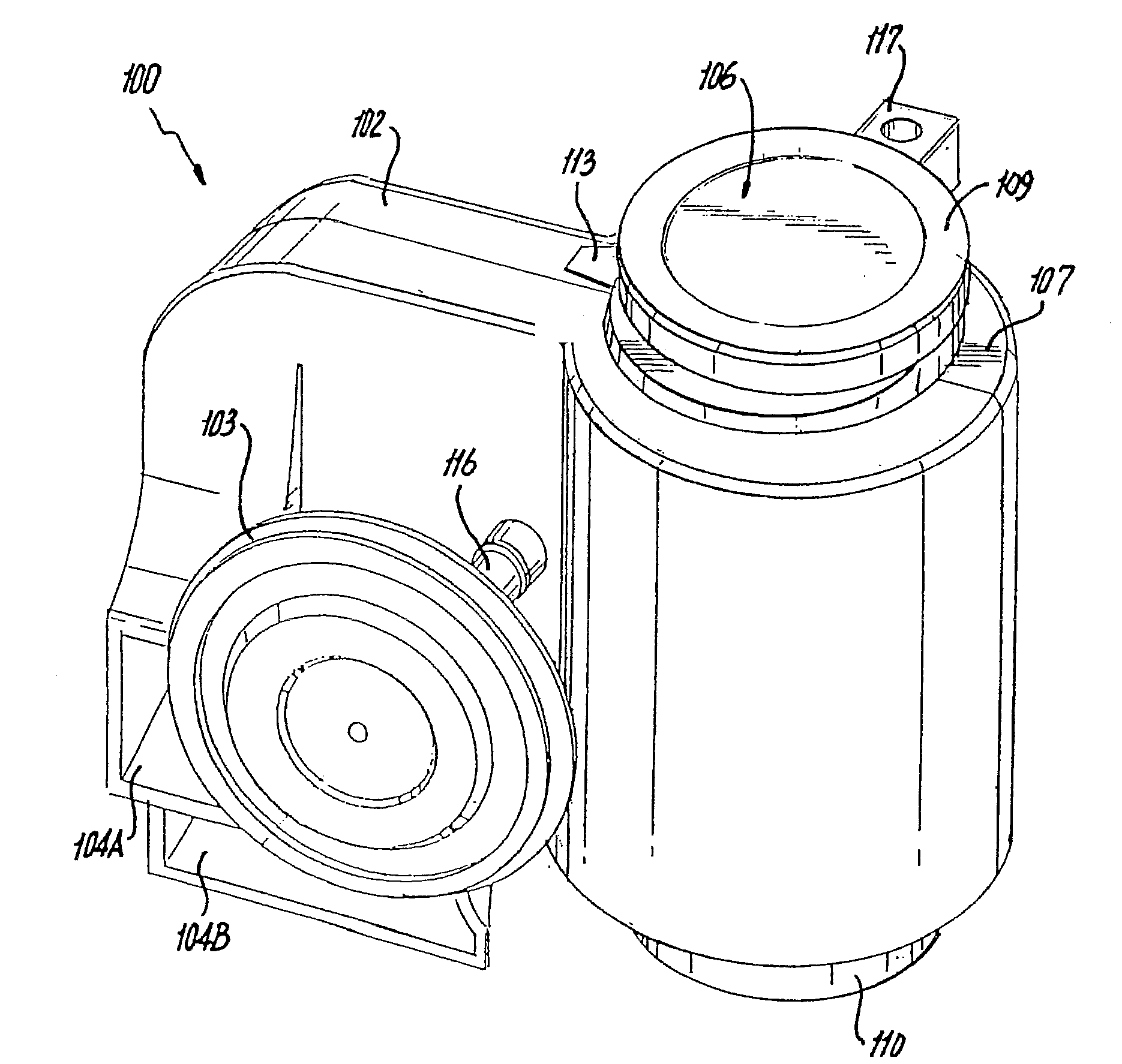
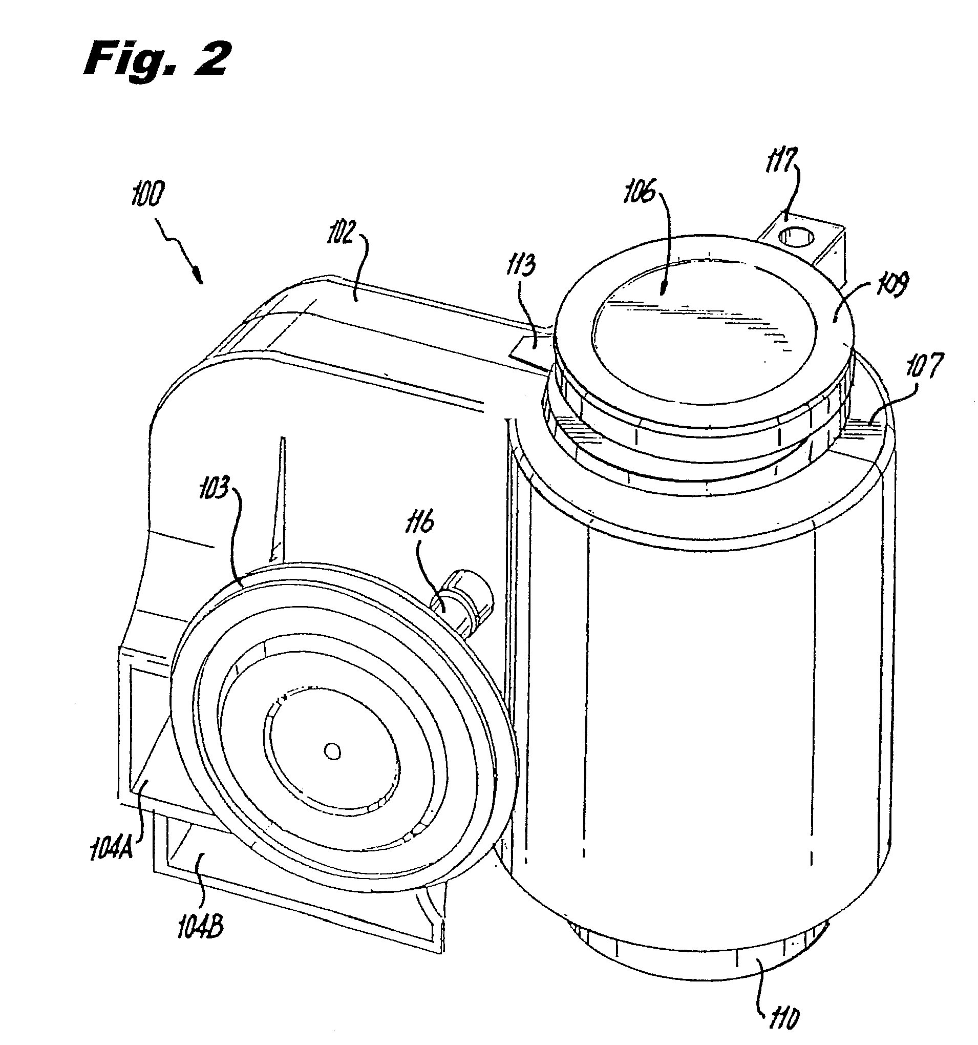
[0068]Referring now to FIGS. 2, 2A, 3, and 4 an alternative embodiment of an electropneumatic horn has been provided that overcomes at least one of the detriments in the rela...


PUM


Abstract

The present electric horn system includes a monolithic rigid housing member having a receiving opening for fixably housing, in an non-removable and secure manner following assembly, a compressor member, thereby preventing unintended separation and improving a reliability of the electric horn system. An acoustic sound wave generator includes an acoustic duct chambering system associated throughout with the monolithic rigid housing member. The acoustic sound wave generator receives compressed air from the compressor member to produce sound and propagate the same externally. A horn mounting system enables ready attachment of the system to a consumer-desired surface; either mechanically, magnetically, adhesively or via any other known attachment or mounting system. Optional weather and water resistant systems prohibit unintended water access to the electric horn system enabling use of the system in exposed weather conditions for improved user convenience.

Description

CROSS REFERENCE TO RELATED APPLICATIONS[0001]This application cross references and claims priority from U.S. Prov. App. Ser. Nos. 60 / 970,365 filed Sep. 6, 2007, 60 / 979,525 filed Oct. 12, 2007, and 61 / 059,172 filed Jun. 5, 2008, the entire contents of each of which are also incorporated herein by reference.FIGURE SELECTED FOR PUBLICATION[0002]FIG. 8BACKGROUND OF THE INVENTION[0003]1. Field of the Invention[0004]The present invention relates to an electric horn system. More specifically, the present invention relates to an electropneumatic horn system adapted for multiple commercial uses wherein a compressed air generating unit is securely fixed within a monolithic housing during an assembly and enables multi-tonal, particularly bi-tonal sound generation, during a use.[0005]2. Description of the Related Art[0006]The related art involves generally electric and electropneumatic horn constructions and systems. Electropneumatic horns are those which generate sound by generated air flow or...

Claims


Application Information

Patent Timeline
Patent Type & Authority Patents(United States)
IPC IPC(8): G10K9/04G10K9/12
CPCG10K9/04
Inventor SOLOW, STANLEY
Owner WOLO MFG
Why Eureka
Try Eureka