Mechanical locking system for panels and method of installing same

a locking system and locking system technology, applied in the direction of mechanical apparatus, walls, resiliently-mounted floors, etc., can solve the problems of high material cost, difficult to bend wood-based materials, complicated snap connection, etc., and achieve high snapping resistance, high friction, and simple horizontal displacement

Active Publication Date: 2010-11-30
VÄLINGE INNOVATION AB
View PDF197 Cites 249 Cited by
  • Summary
  • Abstract
  • Description
  • Claims
  • Application Information

AI Technical Summary

Benefits of technology

[0012]A first overall objective is to provide a locking system, which could be locked by horizontal snapping and with less snapping resistance than the known systems. The costs and functions should be favourable compared to known technology. An aspect of the overall objective is to improve the function and costs of those parts of the locking system that locks in the horizontal direction when panels are pushed against each other.
[0013]More specifically an object is to provide a snap locking system where one or several of the following advantages are obtained.
[0015]The locking function should be reliable and the vertical and horizontal locking should be strong and prevent that two locked panels will move when humidity is changing or when people walk on a floor.
[0017]The locking system should be designed in such a way that the material and production costs could be low.
[0021]The embodiment allows horizontal and vertical locking of all sides of floor panels with for instance an angling of the long sides, a simple horizontal displacement along the long sides and snapping of the short sides. In this preferred embodiment the flexible locking element is on the short sides. It could be on the long side or on the long and short sides.
[0022]The invention is especially suited for use in floor panels, which are difficult to snap for example because they have a core, which is not flexible, or strong enough to form a strong snap locking system. The invention is also suitable for wide floor panels, for example with a width larger than 20 cm, where the high snapping resistance is a major disadvantage during installation, in panels where parts of the locking system is made of a material with high friction, such as wood and in locking systems which are produced with tight fit or without play or even with pretension. Especially panels with such pretension where the locking strip is bent in locked position and presses the panels together are very difficult to displace and snap. A locking system that reduces the snapping resistance will decrease the installation time of such panels considerably.

Problems solved by technology

Such a snap connection is complicated since a hammer and a tapping block is frequently used to overcome the friction between the long edges and to bend the strip during the snapping action.
Wood based materials are generally difficult to bend.
The material cost is therefore high and the locking system is generally not compatible with the locking system used in old panels.
It is difficult to fix the plastic strip over the whole length of the short side.
This means that corner portions will not have any tongue and this could cause problems in some applications.
Especially panels with such pretension where the locking strip is bent in locked position and presses the panels together are very difficult to displace and snap.
A locking system that reduces the snapping resistance will decrease the installation time of such panels considerably.

Method used


Image

  • Mechanical locking system for panels and method of installing same
  • Mechanical locking system for panels and method of installing same
  • Mechanical locking system for panels and method of installing same

Examples


Embodiment Construction

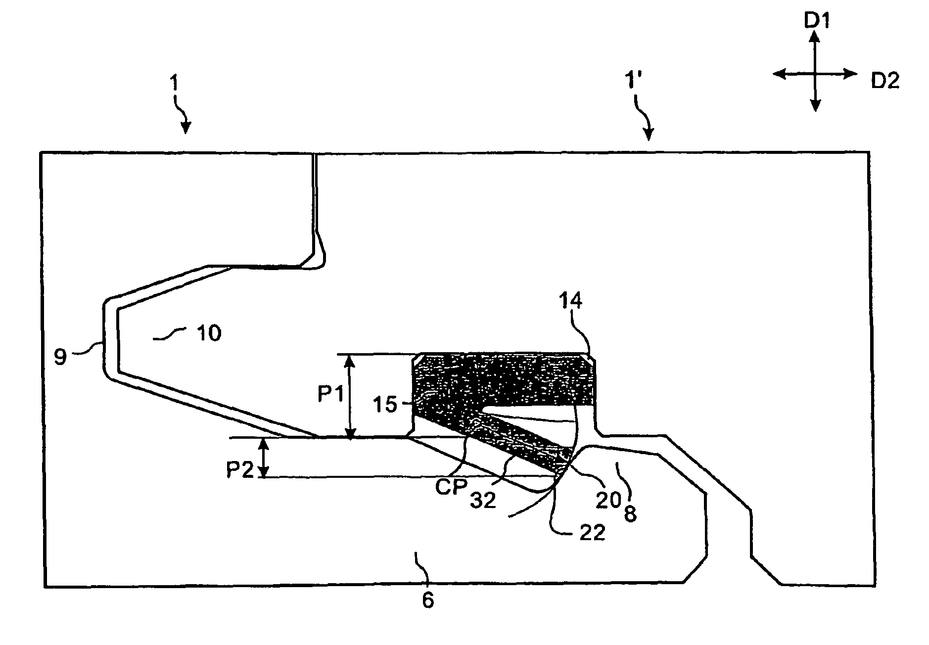
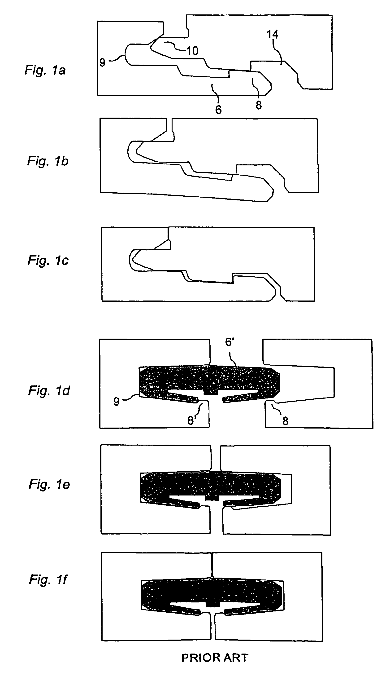
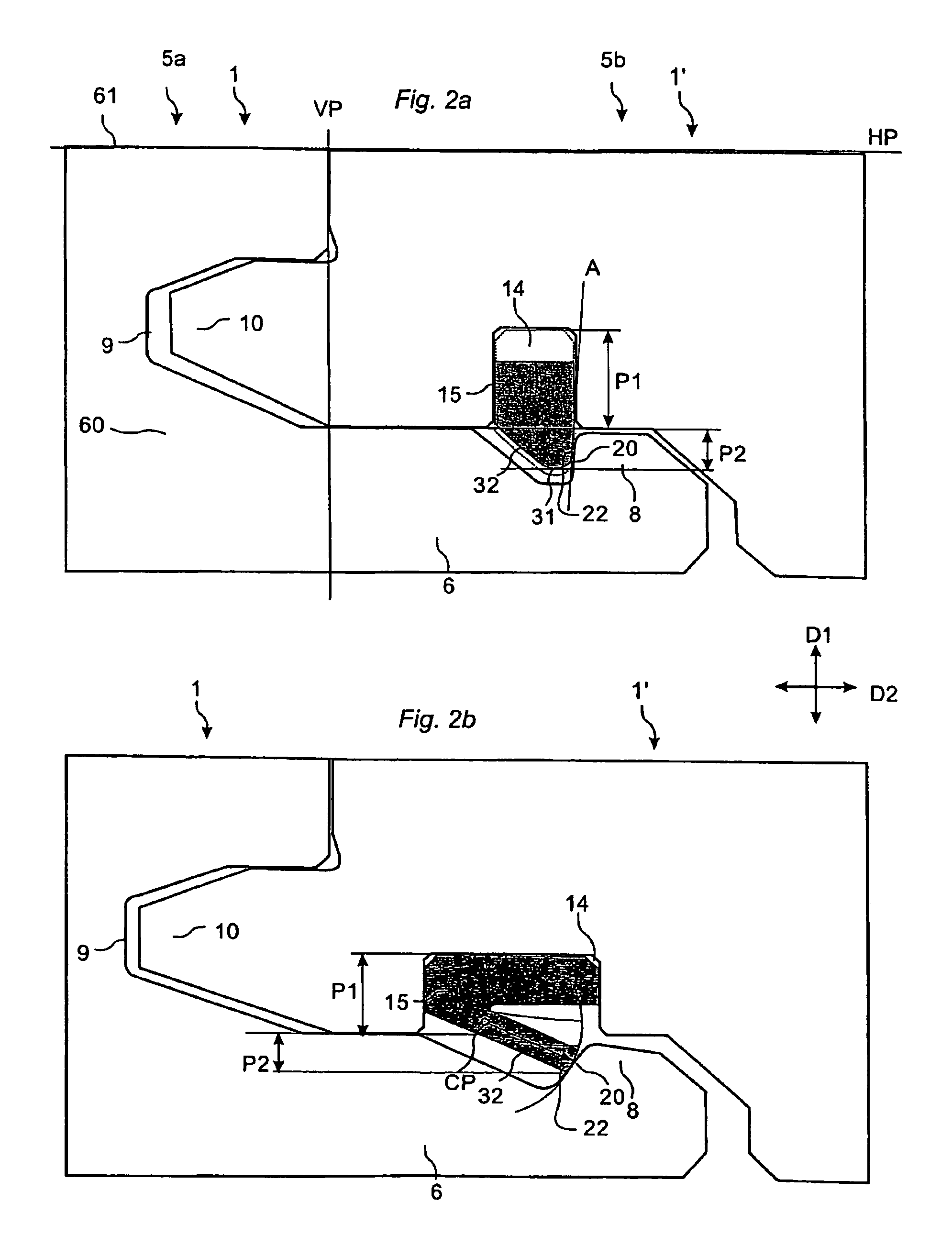
[0033]To facilitate understanding, several locking systems in the figures are shown schematically. It should be emphasised that improved or different functions can be achieved using combinations of the preferred embodiments. The inventor has tested all known and especially all commercially used locking systems on the market in all types of floor panels, especially laminate and wood floorings and the conclusion is that at least all these known locking systems which have one or more locking elements cooperating with locking grooves could be adjusted to a system with one or more flexible locking elements according to the invention. Most of them could easily be adjusted in such a way that they will be compatible with the present systems. Several flexible locking elements could be located in both adjacent edges, one over the other or side-by-side. The flexible locking element could be on long and / or short sides and one side with a flexible locking element could be combined with an other ...


PUM


Abstract

Floor panels are provided with a mechanical locking system including a flexible locking element in a locking groove, which during a horizontal motion is displaced vertically.

Description

CROSS-REFERENCE TO RELATED APPLICATIONS[0001]The present application is a continuation of U.S. Ser. No. 11 / 092,748, filed on Mar. 30, 2005, U.S. Ser. No. 11 / 575,600, filed on Mar. 20, 2007, which is a national stage application of PCT / SE2005 / 001586 and U.S. Ser. No. 11 / 577,628, filed on Apr. 1, 2007, which is a national stage application of PCT / SE2005 / 001586. The entire contents of U.S. Ser. No. 11 / 092,748, U.S. Ser. No. 11 / 575,600 and U.S. Ser. No. 11 / 577,628 are hereby incorporated herein by reference.TECHNICAL FIELD[0002]The invention generally relates to the field of mechanical locking systems for floor panels and building panels.FIELD OF APPLICATION OF THE INVENTION[0003]The present invention is particularly suitable for use in floating floors, which are formed of floor panels which are joined mechanically with a locking system integrated with the floor panel, i.e., mounted at the factory, are made up of one or more upper layers of veneer, decorative laminate or decorative plas...

Claims


Application Information

Patent Timeline
Patent Type & Authority Patents(United States)
IPC IPC(8): E04B2/20
CPCE04F15/02038E04B5/00E04F21/22E04F15/04E04F2201/0115E04F2201/0138E04F2201/0146E04F2201/0153E04F2201/0176E04F2201/023E04F2201/042E04F2201/0523E04F2201/0547E04F2201/0576E04F2201/0582E04F2201/0588F16B5/0076F16B5/008E04F15/02F16B5/00E04F15/00E04B1/5818E04B1/541
Inventor PERVAN, DARKOHAKANSSON, NICLASNYGREN, PER
Owner VÄLINGE INNOVATION AB
Why Eureka
Try Eureka