Directional safety vest

a safety vest and directional technology, applied in the field of safety vests, can solve the problem that prior art does not teach simultaneously showing the first fluorescent color on the front panel

Inactive Publication Date: 2010-12-07
GREER RONALD H
View PDF15 Cites 21 Cited by
  • Summary
  • Abstract
  • Description
  • Claims
  • Application Information

AI Technical Summary

Benefits of technology

[0016]The present invention provides a directional safety vest that includes a vest body adapted to cover a human torso. A front panel of the vest has a first fluorescent color. A back panel of the vest body has a second fluorescent color which is different from the first fluorescent color.
[0017]A

Problems solved by technology

However, the prior art does not teach simultaneously showing a first fluorescent color on a front

Method used


Image

  • Directional safety vest
  • Directional safety vest
  • Directional safety vest

Examples


Embodiment Construction

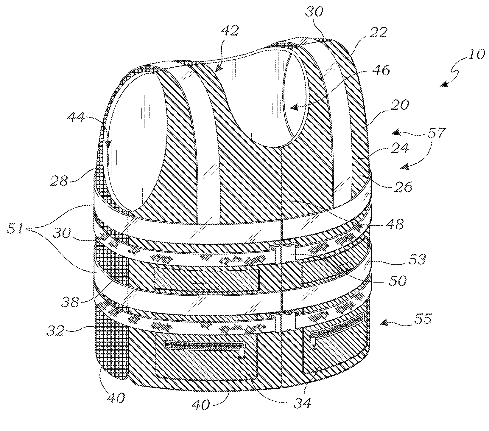
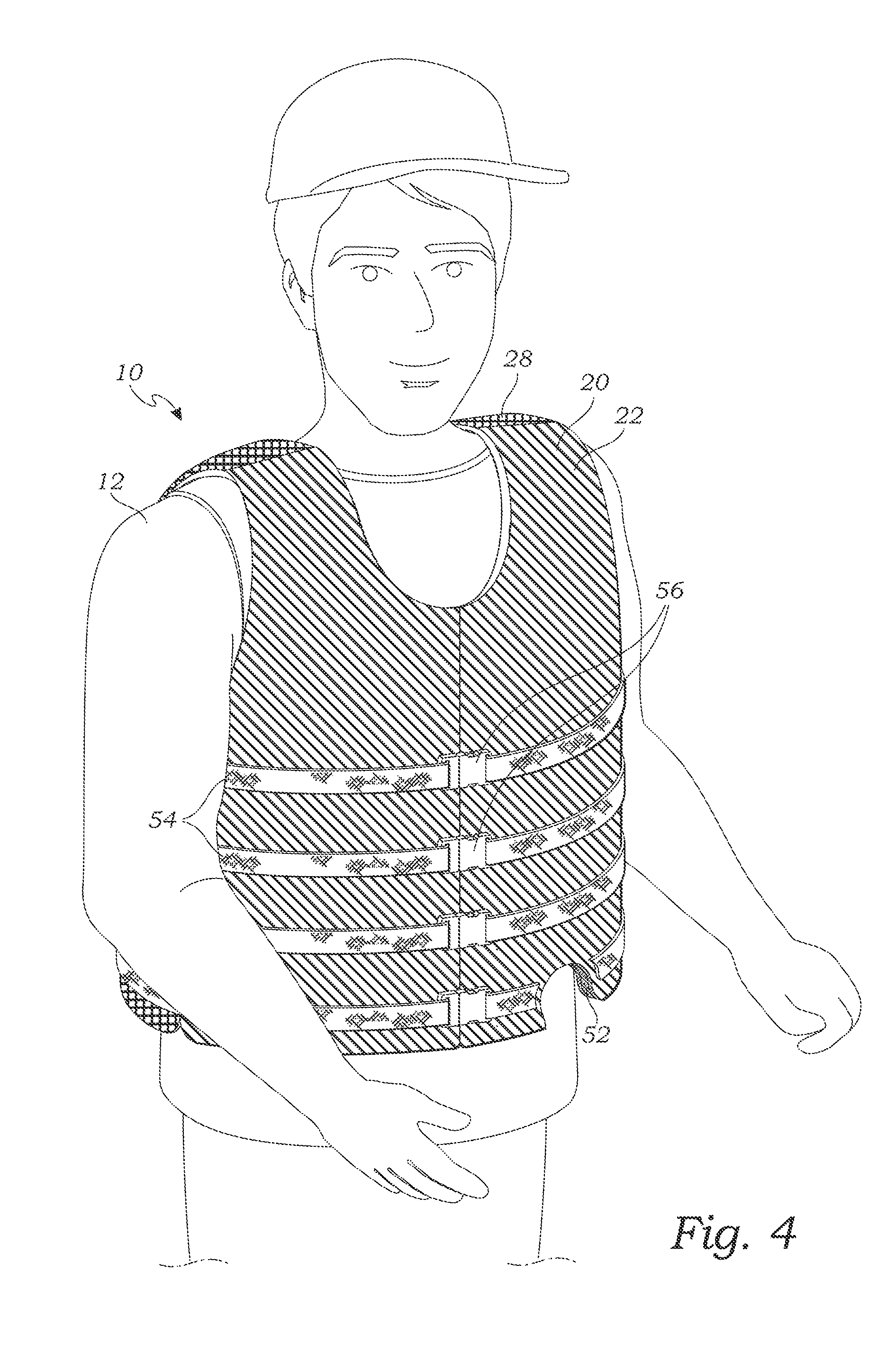
[0026]The above-described drawing figures illustrate the invention, a directional safety vest 10. The directional safety vest 10, works to indicate to observers the orientation of a person 12 wearing the safety vest 10. This can be useful in different situations; for example, on a construction site, the orientation of the person 12 may help others to determine what the person is doing and whether he or she might be in danger. When the person 12 is in the water, the orientation of the person 12 may indicate whether the person 12 is in danger, and if a rescue is required, it may help determine how the rescue should take place.

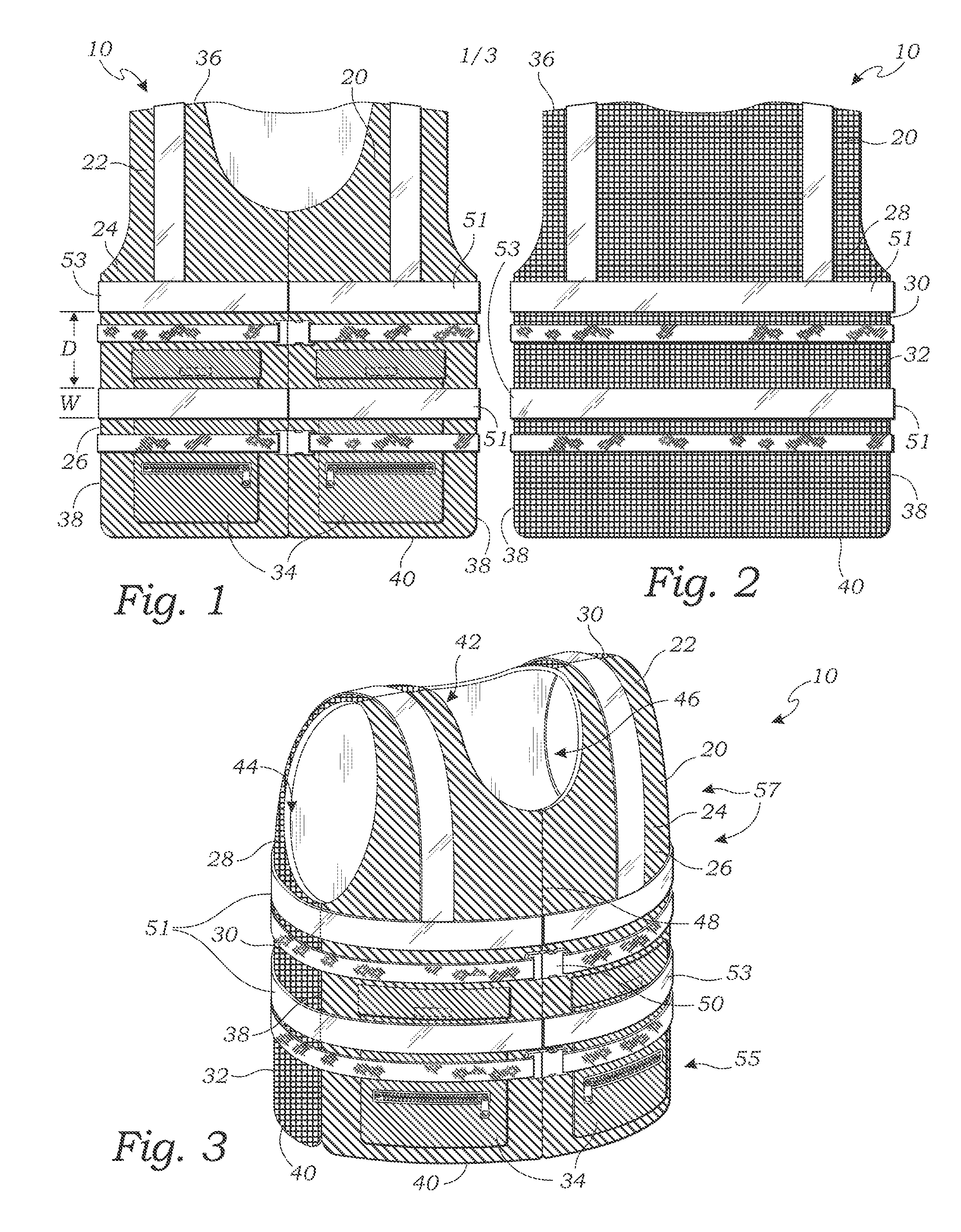
[0027]FIG. 1 is a front view of the safety vest 10 according to an embodiment of the present invention, and FIG. 2 is a back view thereof. As shown in FIGS. 1 and 2, the safety vest 10 has a vest body 20 adapted to cover a human torso. A front panel 22 of the vest body 20 is constructed of a first high visibility fabric 24 having a first fluorescent color 26. A b...


PUM


Abstract

A directional safety vest has a vest body adapted to cover a human torso. A front panel of the vest has a first fluorescent color. A back panel of the vest body has a second fluorescent color which is different from the first fluorescent color.

Description

CROSS-REFERENCE TO RELATED APPLICATIONS[0001]Not ApplicableSTATEMENT REGARDING FEDERALLY SPONSORED RESEARCH[0002]Not ApplicableBACKGROUND OF THE INVENTION[0003]1. Field of the Invention[0004]This invention relates generally to safety vests, and more particularly to a directional safety vest that facilitates rescues based upon different fluorescent colors provided on the front and back of the vest.[0005]2. Description of Related Art[0006]The following art defines the present state of this field:[0007]Garvey, U.S. Pat. No. 6,182,291, teaches a hunting vest having a base fabric material. Flaps are provided on the front and on the back of the vest. The flaps are specifically designed to have a camouflage color on one side, and a blaze orange color on the opposite side. The flaps are detachably attached to the vest so that either color is visible, dependent on the choice of the hunter. It is possible to configure the Garvey vest so that the front is a bright fluorescent color and the bac...

Claims


Application Information

Patent Timeline
IPC IPC(8): A41D13/00
CPCA41D13/01B63C9/11
Inventor GREER, RONALD H.
Owner GREER RONALD H
Why Eureka
Try Eureka