Calf stretcher

a calf stretcher and calf technology, applied in the field of calf stretchers, can solve the problems of not necessarily the most orthopedically correct way of stretching the calf muscles

Inactive Publication Date: 2010-12-28
TSAKIRIS PETER
View PDF20 Cites 9 Cited by
  • Summary
  • Abstract
  • Description
  • Claims
  • Application Information

AI Technical Summary

Benefits of technology

[0008]An object of the present invention is to provide for a novel calf stretcher which orthopedically positions the user's leg, calf, ankle and foot in the proper position for properly stretching and flexing of the calf muscle and tendons of the lower leg.
[0009]Another object of the present invention is to provide for a novel calf stretcher which is cooperable with the corner of a room, the intersection of a floor and wall, which allows the user to properly stretch or flex the calf muscles.SUMMARY OF THE INVENTION

Problems solved by technology

The calf muscles and lower leg tendons in particular need to be stretched and warmed because they are highly susceptible to cramping.
Most commonly one would lean against the wall and stretch the legs, which is not necessarily the most orthopedically correct manner of stretching the calf muscles.

Method used


Image

  • Calf stretcher
  • Calf stretcher
  • Calf stretcher

Examples


Embodiment Construction

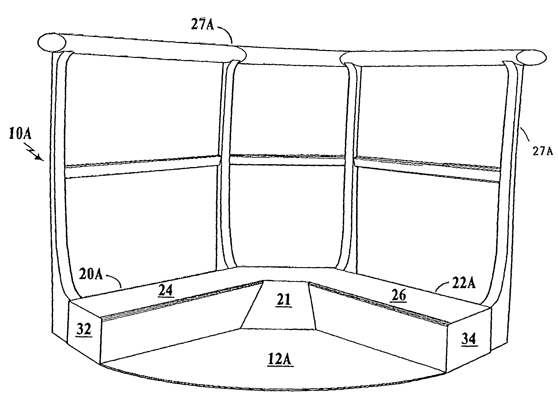
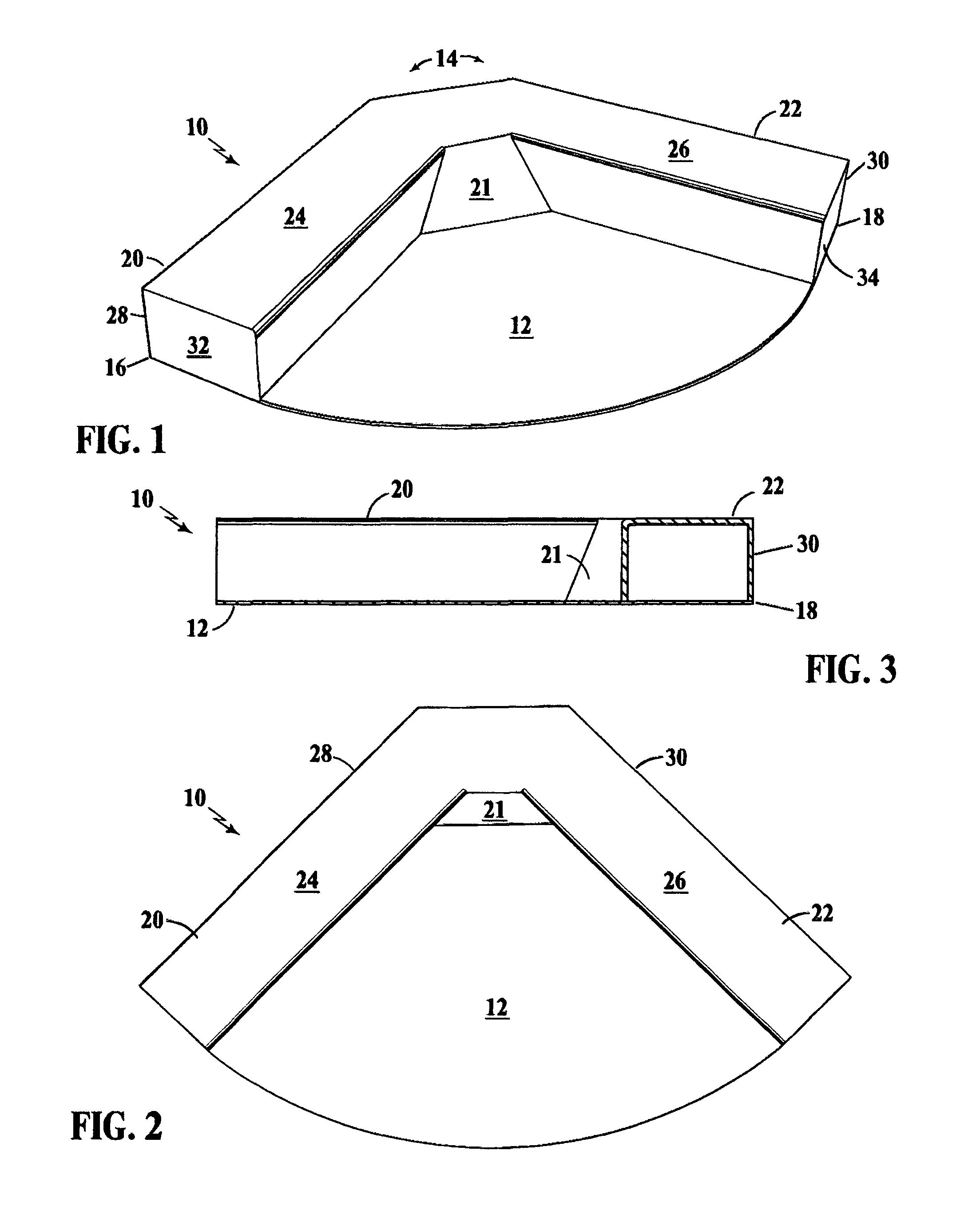
[0020]FIG. 1 is a perspective view of a corner unit calf stretcher 10, FIG. 2 is a top view of the corner unit calf stretcher 10 of FIG. 1, and FIG. 3 is a side view. Corner unit calf stretcher 10 is formed with a base member 12, base member 12 having formed thereon, at least one planar 90 degree angle 14 defined by two 90 degree edges 16 and 18. Emanating from corner angle 14, are two upstanding curbs 20 and 22 having non-skid surfaces on their upper planar surfaces 24 and 26. The side walls 28 and 30 of upstanding curbs 20 and 22 along with the edges 16 and 18 of base member 12 in one embodiment, engage the intersection of two abutting walls and the floor upon which the base member is supported. In this configuration, the individual may stand on base member 12 and place the toe portion of the selective right foot, left foot, or both onto the upstanding curbs 20 and 22 in order to achieve the desired angle of the foot in order to lower the heel portion of the foot lower than the pl...


PUM


Abstract

A device for stretching or flexing the calf muscles and tendons of the lower leg, the device in one embodiment having a base member formed with a 90 degree angle for positioning at the intersection of two walls and a floor, the base member having elevated non-skid planar surfaces emanating from the 90 degree angle to the edge of the base plate allowing a user to stand on the elevated non-skid surfaces with both feet and use one's body weight to stretch the calf muscles by lowering or raising ones heels below or above the plane of the elevated non-skid surface. In another embodiment, the device consists of a base member having a straight wall engaging edge with an upstanding wall, terminating in a flat planar surface and an angled ramp surface communicating between the flat upper surface and the base member, the calf stretcher allowing the user to stand on the base member and place selective right or left foot onto the ramp section for the respective stretching of the calf. Either embodiment may be used cooperatively with a wall or as a stand alone apparatus and may incorporate a stable hand rail.

Description

RELATED APPLICATIONS[0001]Applicant claims the benefit of provisional application Ser. No. 61 / 188,067, filed Aug. 6, 2008.BACKGROUND OF THE INVENTION[0002]1. Field of the Invention[0003]The present invention relates to exercise equipment, and more particularly, to a stretching device which allows for the user to stretch or flex their calf muscles and tendons of the lower legs.[0004]2. Description of the Prior Art[0005]Most exercise activities require some use of the legs in performing the activity. Running is almost totally a leg activity. However, weight lifters in the gym use their legs significantly when performing lifting exercises. Gymnasts utilize their legs in a significant number of the activities which they perform, as do martial arts practitioners. In any exercise activity it is desirous that the muscles be warmed up and stretched so to perform at optimal efficiency and to avoid possible injury or cramping. The calf muscles and lower leg tendons in particular need to be st...

Claims


Application Information

Patent Timeline
Patent Type & Authority Patents(United States)
IPC IPC(8): A63B23/04A63B21/068
CPCA63B21/00047A63B23/08A63B2208/0204Y10S482/907
Inventor TSAKIRIS, PETER
Owner TSAKIRIS PETER
Why Eureka
Try Eureka