MEMS fuze assembly

a technology of electronic components and fuzes, applied in ammunition fuzes, lighting and heating apparatus, instruments, etc., can solve the problems of high cost, lower reliability, and high complexity, and achieve the effect of leaving more space for electronics and explosive materials

Inactive Publication Date: 2011-03-29
THE UNITED STATES OF AMERICA AS REPRESENTED BY THE SECRETARY OF THE NAVY
View PDF9 Cites 13 Cited by
  • Summary
  • Abstract
  • Description
  • Claims
  • Application Information

AI Technical Summary

Benefits of technology

[0008]It is an object of the present invention to provide a fuze assembly that is over 100 times smaller than conventional detonators, thus leaving more space for electronics and explosive material.

Problems solved by technology

Such detonators are much too large for use in MEMS type fuzes and, in addition, they require assembly of multiple mechanical components resulting in higher complexity, higher costs and lower reliability.

Method used


Image

  • MEMS fuze assembly
  • MEMS fuze assembly
  • MEMS fuze assembly

Examples


Embodiment Construction

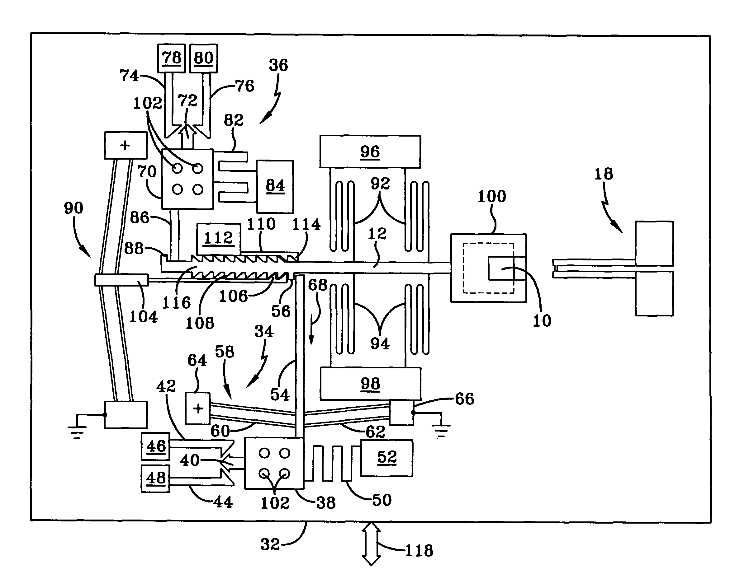
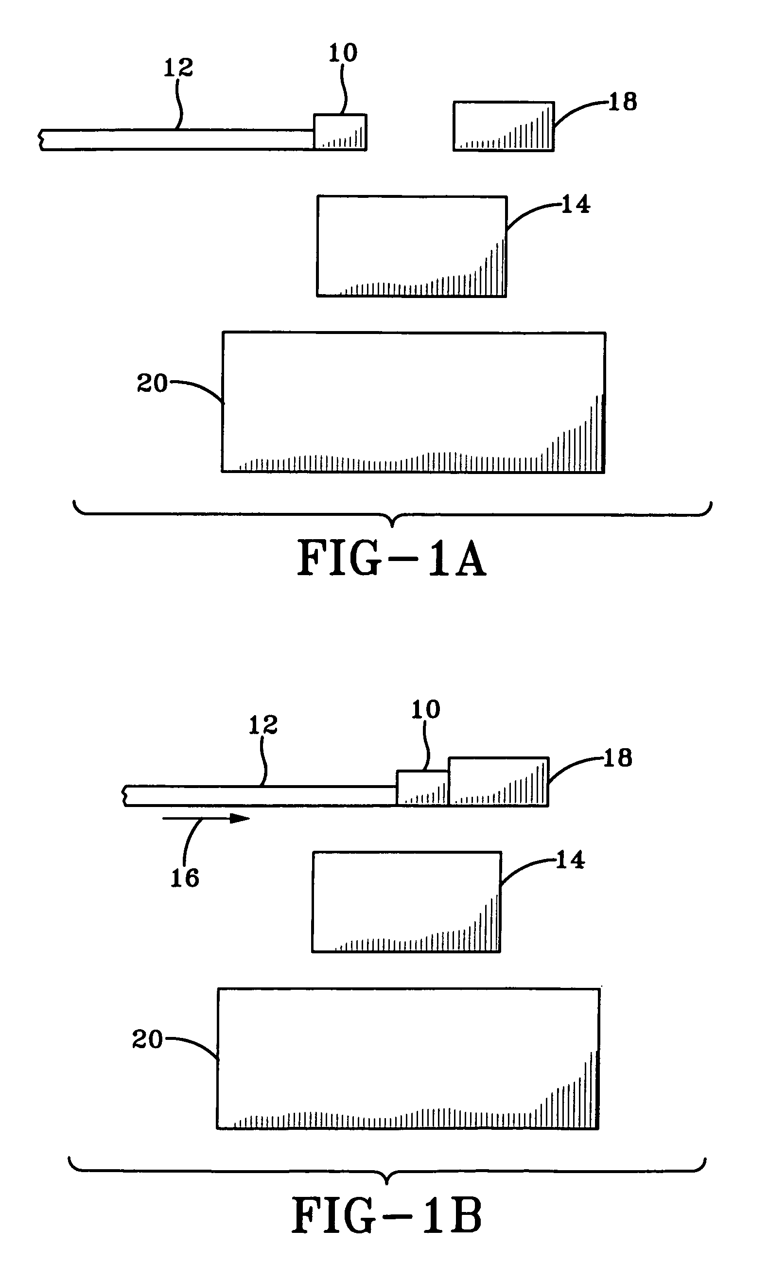
[0014]FIGS. 1A and 1B illustrate a microdetonator and its placement for initiating a charge sequence. In FIG. 1A, a microdetonator 10 is carried by a slider 12 and is in an initial position insufficient to set off a secondary explosive 14, also known as a secondary lead.

[0015]When the slider 12 moves to the right as indicated in FIG. 1B by arrow 16, microdetonator 10 may be adjacent an initiator 18 and directly above secondary lead 14, whereupon the microdetonator 10 may be initiated or detonated by the initiator 18. Secondary lead 14 may be initiated by the microdetonator 10 and set off a main explosive charge 20, which is the main charge of the munitions round in which the apparatus is imbedded. Movement of slider 12 may be inertial, such as upon impact with a target, or may be mechanical, as will be described herein.

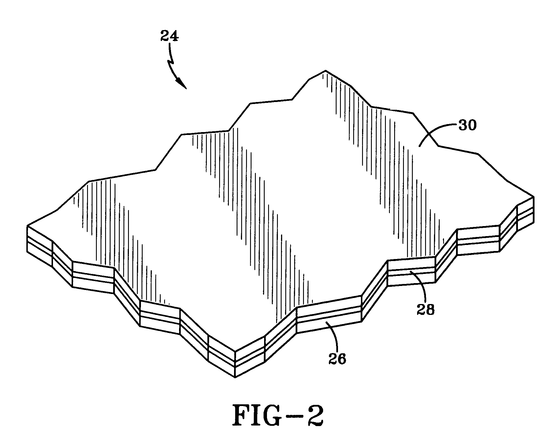
[0016]FIG. 2 illustrates a portion of an SOI wafer 24 from which the MEMS fuze assembly of the present invention is fabricated. The structure of FIG. 2 includes, in a...


PUM


Abstract

A MEMS fuze having a moveable slider with a microdetonator at an end for positioning adjacent an initiator. A setback activated lock and a spin activated lock prevent movement of the slider until respective axial and centrifugal acceleration levels have been achieved. Once these acceleration levels are achieved, the slider is moved by a V-beam shaped actuator arrangement to position the microdetonator relative to a secondary lead to start an explosive train in a munitions round.

Description

[0001]The present application is a Continuation Application of prior U.S. patent application Ser. No. 11 / 894,628 filed on Jul. 31, 2007 now U.S. Pat. No. 7,552,681.STATEMENT OF GOVERNMENT INTEREST[0002]The invention described herein may be manufactured and used by or for the Government of the United States of America for Governmental purposes without the payment of any royalties thereon or therefor.BACKGROUND OF THE INVENTION[0003]1) Field of the Invention[0004]The invention relates in general relates to MEMS (microelectromechanical systems) devices and more particularly to a MEMS fuze utilized to set off a main charge of a munitions round.[0005]2) Description of the Related Art[0006]A fuze is a device designed to set off an explosive train in a munitions round such as a mortar round, artillery shell or rocket warhead, by way of example. Conventional mechanical fuzes make use of a detonator, such as an M100, which is cylindrical and approximately 3 mm (millimeters) in diameter and 1...

Claims


Application Information

Patent Timeline
Patent Type & Authority Patents(United States)
IPC IPC(8): F42C15/34
CPCF42C15/005F42C15/184F42C15/20F42C15/21F42C15/24F42C15/34F42C15/40
Inventor FAN, LAWRENCEBEGGANS, MICHAELCHEN, EZRALAIB, GERALDOLSON, DAVIDJEAN, DANIELHENDERSHOT, JOHN
Owner THE UNITED STATES OF AMERICA AS REPRESENTED BY THE SECRETARY OF THE NAVY
Why Eureka
Try Eureka