
System and method for identifying complex tokens in an image

a technology of complex tokens and image, applied in image analysis, image enhancement, instruments, etc., can solve the problems of significant possibilities of false positives and false negatives in shadow recognition, and achieve the effect of accurately and accurately identifying regions

Active Publication Date: 2011-08-09
INNOVATION ASSET COLLECTIVE
View PDF29 Cites 15 Cited by
  • Summary
  • Abstract
  • Description
  • Claims
  • Application Information

AI Technical Summary

Benefits of technology

[0002]The present invention provides a method and system comprising image techniques that accurately and correctly identify regions of an image that correspond to a single material in a scene depicted in the image.

Problems solved by technology

A challenge in the utilization of computers to accurately and correctly perform operations relating to images is the development of algorithms that truly reflect and represent physical phenomena occurring in the visual world.
For example, the ability of a computer to correctly and accurately distinguish between a shadow and a material object edge within an image has been a persistent challenge to scientists.
While this approach can be implemented by algorithms that can be accurately executed by a computer, the results will often be incorrect.
Thus, when utilizing conventional techniques for shadow and object edge recognition, there are significant possibilities for false positives and false negatives for shadow recognition.

Method used


Image

  • System and method for identifying complex tokens in an image
  • System and method for identifying complex tokens in an image
  • System and method for identifying complex tokens in an image

Examples


Embodiment Construction

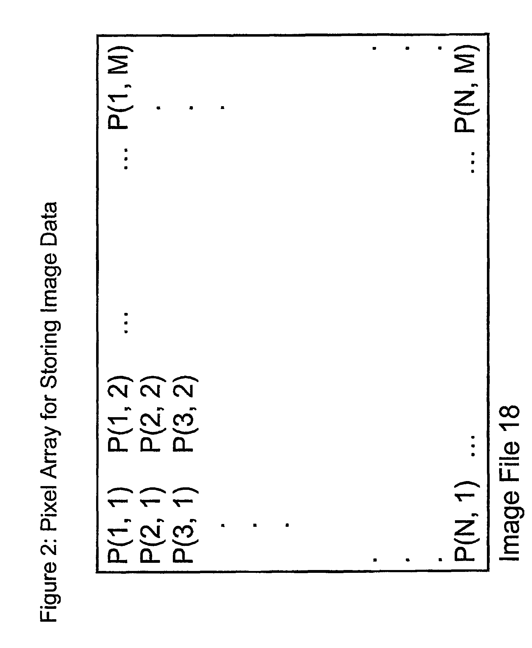
FIG. 10c is an illustration of a 7×7 pixel patch within the n×m pixel array image file of FIG. 2.

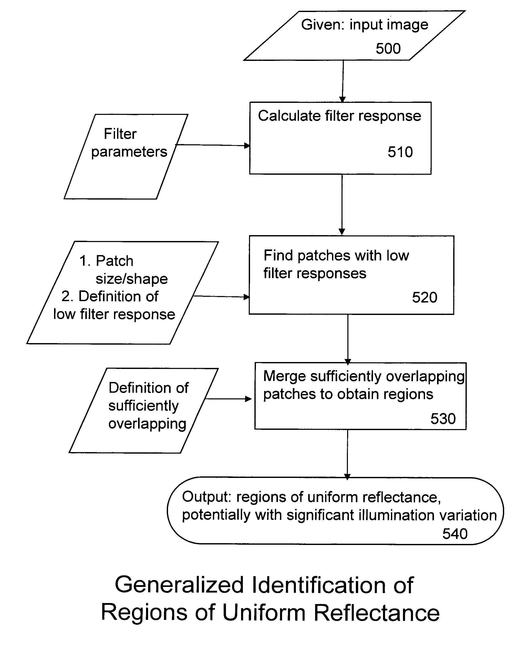
[0021]FIG. 11 is a flow chart for identifying regions of uniform material reflectance within the n×m pixel array image file of FIG. 2, according to a feature of the present invention.

[0022]FIG. 12 is a flow chart for combining results from executions of the routine of FIG. 11 with differing parameters, according to a feature of the present invention.

DETAILED DESCRIPTION OF THE PREFERRED EMBODIMENTS

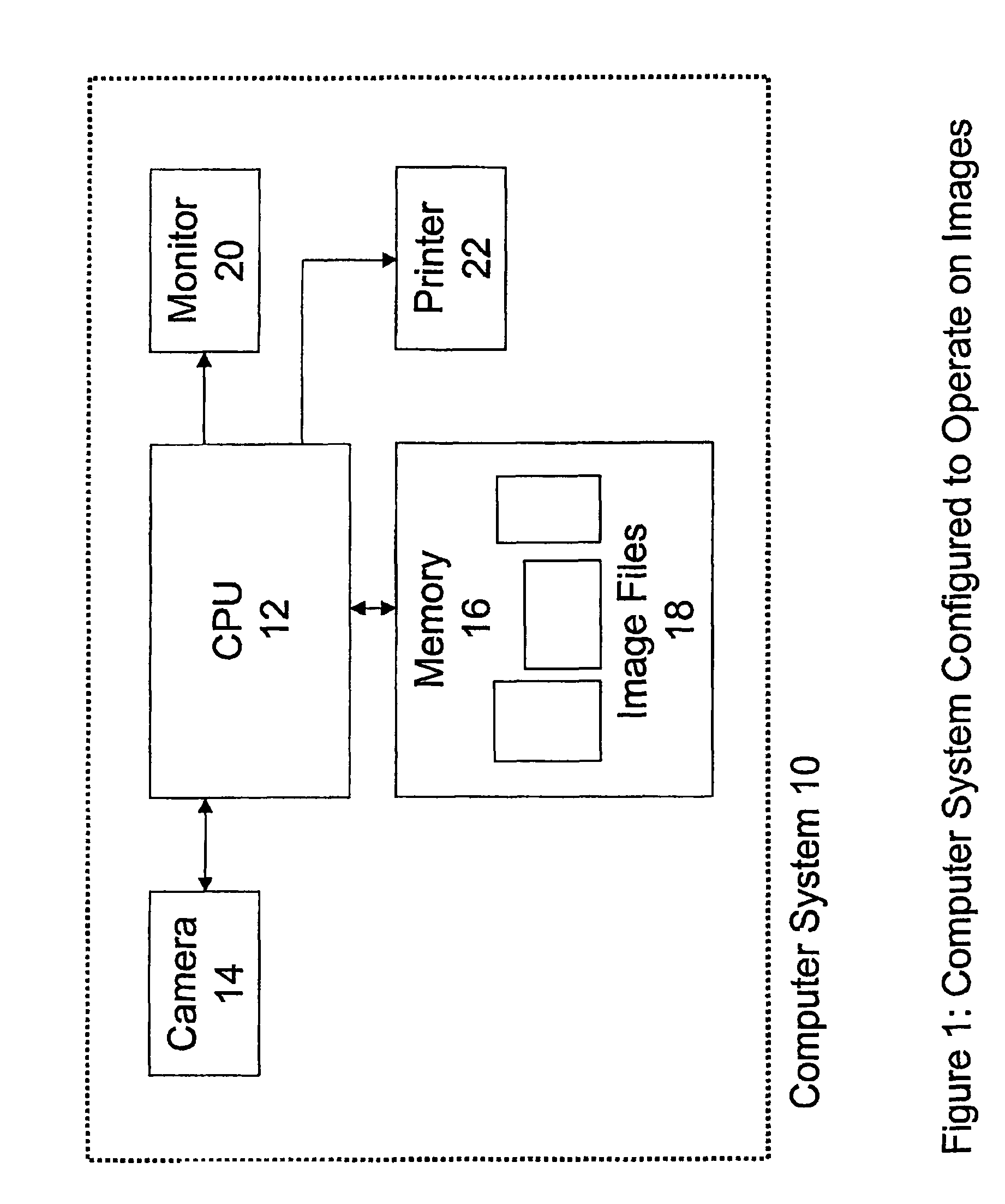
[0023]Referring now to the drawings, and initially to FIG. 1, there is shown a block diagram of a computer system 10 arranged and configured to perform operations related to images. A CPU 12 is coupled to a device such as, for example, a digital camera 14 via, for example, a USB port. The digital camera 14 operates to download images stored locally on the camera 14, to the CPU 12. The CPU 12 stores the downloaded images in a memory 16 as image files 18. The image files 18 can be accessed by the...


PUM


Abstract

In a first exemplary embodiment of the present invention, an automated, computerized method is provided for processing an image. According to a feature of the present invention, the method comprises the step of performing a filter response technique to identify patches of uniform reflectance within the image. In a further exemplary embodiment, the method comprises the additional step of utilizing the identified patches of uniform material reflectance to generate single material token regions for use in processing material and illumination aspects of the image.

Description

BACKGROUND OF THE INVENTION[0001]A challenge in the utilization of computers to accurately and correctly perform operations relating to images is the development of algorithms that truly reflect and represent physical phenomena occurring in the visual world. For example, the ability of a computer to correctly and accurately distinguish between a shadow and a material object edge within an image has been a persistent challenge to scientists. An early and conventional approach to object edge detection involves an analysis of brightness boundaries in an image. In the analysis it is assumed that a boundary caused by a material object will be sharp, while a boundary caused by a shadow will be soft or gradual due to the penumbra effect of shadows. While this approach can be implemented by algorithms that can be accurately executed by a computer, the results will often be incorrect. In the real world there are many instances wherein shadows form sharp boundaries, and conversely, material o...

Claims


Application Information

Patent Timeline
Patent Type & Authority Patents(United States)
IPC IPC(8): G06K9/40
CPCG06T7/0081G06T2207/20141G06T2207/20021G06T2207/10024G06T7/11G06T7/187
Inventor FRIEDHOFF, RICHARD MARKSMITH, CASEY ARTHURMAXWELL, BRUCE ALLEN
Owner INNOVATION ASSET COLLECTIVE
Learn More