Differential transmission line connector

a technology of transmission line and connector, which is applied in the direction of pulse conversion, coupling device connection, pulse technique, etc., can solve the problem of unwanted radiation noise that cannot be reduced, and achieve the effect of reducing unwanted radiation nois

Inactive Publication Date: 2011-09-27
PANASONIC CORP
View PDF7 Cites 226 Cited by
  • Summary
  • Abstract
  • Description
  • Claims
  • Application Information

AI Technical Summary

Benefits of technology

[0042]According to the invention, it is possible to maintain a constant length of the signal lines when connecting different differential transmission lines each with three signal lines, and thus signal delays do not occur in the signal lines, and therefore it is possible to provide a differential transmission line connector with little unwanted radiation noise in which the electromagnetic fields of the signals that are transmitted cancel each other out.

Problems solved by technology

However, although compared to ordinary single-end transmission, the differential transmission system of FIGS. 30 and 31 has the numerous above-described merits with regard to high-speed transmission, it requires the two signal lines 912a and 912b in order to transmit a single data bit, and this leads to problems such as more signal lines in order to achieve multiple bit transmission, a thick differential transmission cable 912, and a larger wiring region on the printed circuit boards 916 and 917.
When the three signal lines 912a, 912b, and 912c of the differential transmission cable 912A are disposed as shown in FIG. 33, the distances between the two adjacent signal lines 912a and 912b, and 912b and 912c, and the signal lines 912a and 912c on the sides, are different (L51≠L53, L52≠L53), and this creates a novel problem in that the electromagnetic fields between the signals that are transmitted cannot cancel each other out because the differential impedance cannot be kept constant, and unwanted radiation noise cannot be reduced.

Method used


Image

  • Differential transmission line connector
  • Differential transmission line connector
  • Differential transmission line connector

Examples


first embodiment

[0077]

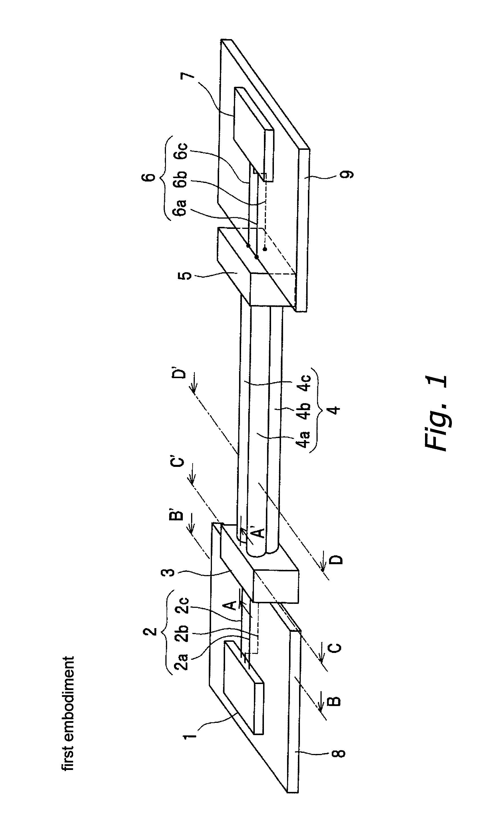
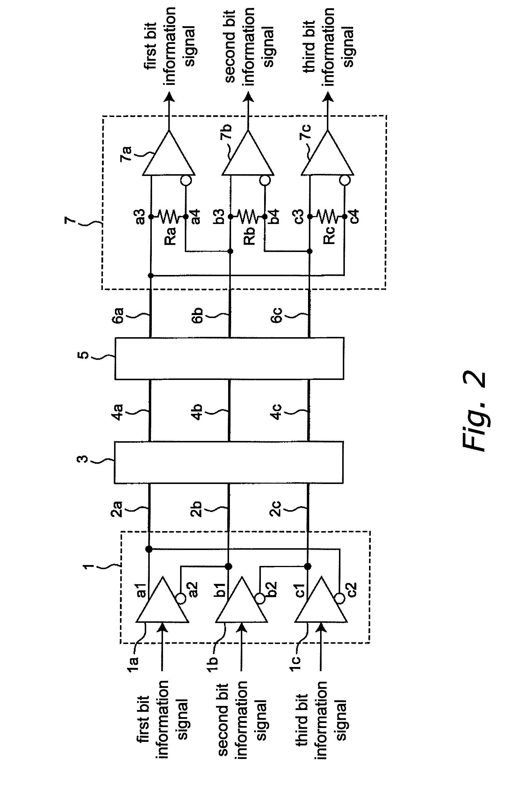
[0078]FIG. 1 is a perspective view showing the structure of a differential transmission system according to a first embodiment of the invention, and FIG. 2 is a circuit diagram of the differential transmission system of FIG. 1. With the differential transmission system of this embodiment, three bit information signals are differentially signaled simultaneously by LVDS (that is, multiple differential transmission is performed) via a differential transmission line that is made of three signal lines. In FIG. 1, the differential driver IC1, which is provided on a first printed circuit board 8, which is a double-sided board, and a differential receiver IC7, which is provided on a second printed circuit board 9, which is a double-sided board and which is different from the first printed circuit board 8, are connected to one another by a differential transmission line that is made from three signal lines. Here, the differential transmission line is made from a differential transmissi...

modified example

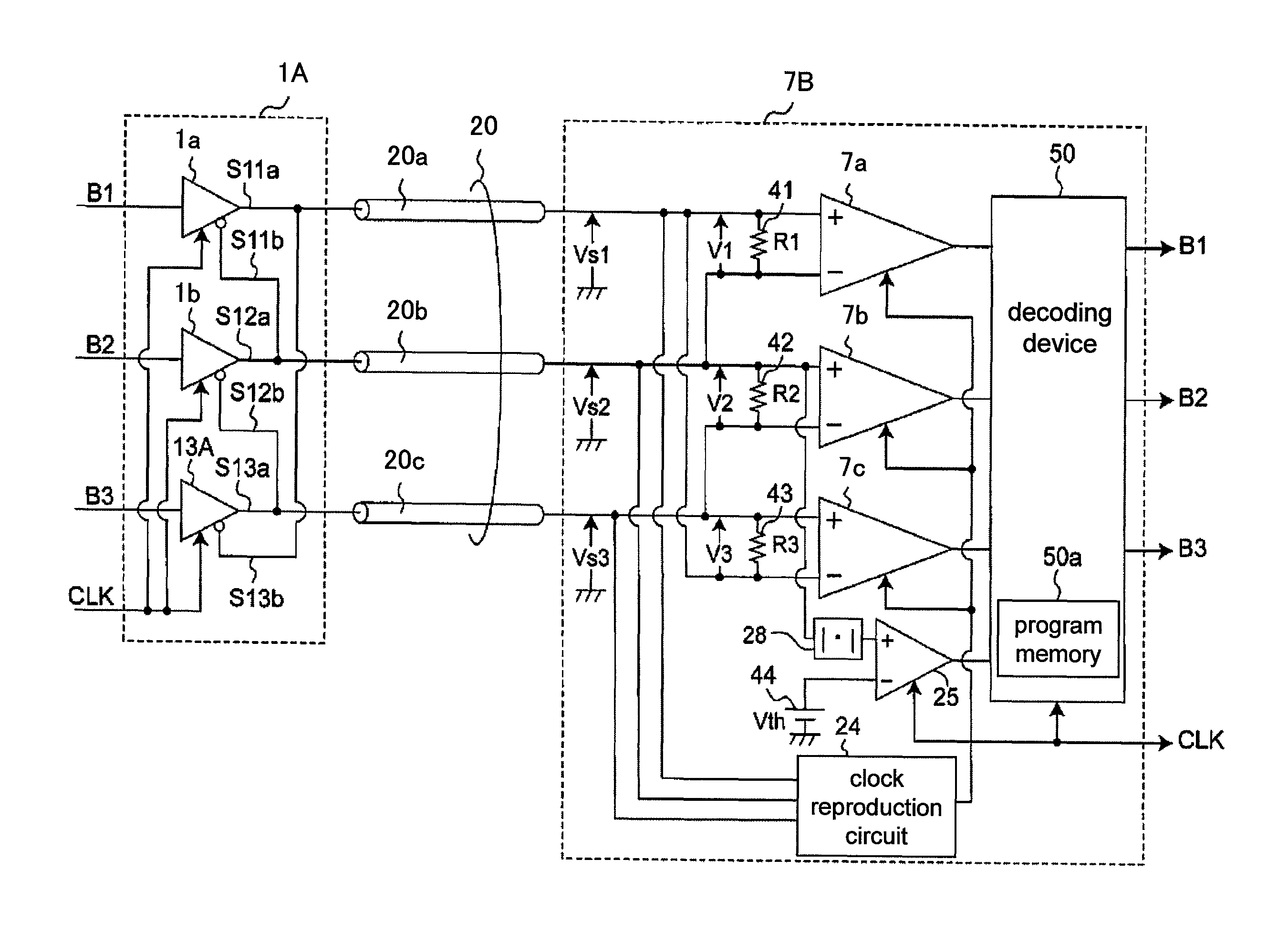
[0136]FIG. 29 is a flowchart that illustrates this example of the bit information determination process that is executed by the decoding device 50 of the signal receiver 7B in a multiple differential transmission system according to a modified example of the third multiple differential transmission system (using the configuration of FIG. 25, differing only in the setting conditions). Here, the structural configuration of the multiple differential transmission system of FIG. 25 is used. The bit information determination process of FIG. 29 differs from the bit information determination process of FIG. 26 only in that the processing of step S13 has been switched with the processing of step S14. This multiple differential transmission system according to a modified example of the third multiple differential transmission system with this configuration has the same actions and effects as the multiple differential transmission system according to the modified example of the second multiple...

second embodiment

[0146]FIG. 7 is a perspective view showing the configuration of a differential transmission system according to a second embodiment of the invention, FIG. 8 is a vertical cross section showing a cut section taken along line H-H′ in FIG. 7, and FIG. 9 is a front view showing the configuration of the connector 3A along the line I-I′ in FIG. 7. This embodiment is characterized in that connectors 3A and 5A that are provided on the upper surface of printed circuit boards 8A and 9A are provided in lieu of the connectors 3 and 5 that were provided on the end surfaces of the printed circuit boards 8 and 9 in the first embodiment.

[0147]The features of the differential transmission line connector 3A according to this embodiment are described below with reference to FIGS. 8 and 9. In this embodiment, the differential transmission pattern 2 of the printed circuit board 8A extends from the output terminals of the differential driver IC1 to a predetermined location on the printed circuit board 8A...


PUM


Abstract

A differential transmission line connector with little unwanted radiation noise is provided. A connector connects a differential transmission pattern for multiple transmission of a group of three differential signals and a differential transmission cable. The differential transmission pattern is provided with three signal lines, and the differential transmission cable also is provided with three signal lines. In a plane that is perpendicular to the longitudinal direction of the differential transmission pattern and the differential transmission cable, the signal lines are positioned at the apexes of an equilateral triangle. The connector is provided with three signal lines that connect, at identical lengths, the signal lines of the differential transmission pattern and the signal lines of the differential transmission cable, between a predetermined first plane of the planes that perpendicularly intersect the longitudinal direction of the differential transmission pattern and a predetermined second plane of the planes that perpendicularly intersect the longitudinal direction of the differential transmission cable.

Description

BACKGROUND OF THE INVENTION[0001]1. Field of the Invention[0002]The present invention relates to differential transmission line connectors for performing multiple differential transmission in which, through the high-speed signal transmission method of differential transmission, the transmission of a plurality of data bits is achieved with a differential transmission line that is provided with few signal lines.[0003]2. Description of the Related Art[0004]Single-end signals that oscillate logically amplitude at the power source voltage have conventionally been used for the transmission of high-speed signals, but the use of low voltage differential signaling (LVDS) has been on the rise due to the increase in the number of drive frequencies and larger bus widths in order to keep up with recent demands for high-speed data transmission, as well as because of its inhibition of unwanted radiation noise and resistance against exogenous noise. With LVDS, generally the differential driver IC i...

Claims


Application Information

Patent Timeline
Patent Type & Authority Patents(United States)
IPC IPC(8): H04B3/00
CPCH04L25/0272H01R13/6461H01R13/6477
Inventor MATSUBARA, RYOFUSAYASU, HIROTSUGUTANIMOTO, SHINICHIHAMADA, SEIJI
Owner PANASONIC CORP
Why Eureka
Try Eureka