Transmission cable

a technology of transmission cable and insulating support, which is applied in the direction of cables, conductive layers on insulating supports, conductors, etc., can solve the problems of increasing the wiring region of printed circuit boards, unable to reduce unwanted radiation noise, and large number, and achieves a constant distance and differential impedance. , the effect of small unwanted radiation nois

Inactive Publication Date: 2010-08-24
PANASONIC CORP
View PDF5 Cites 16 Cited by
  • Summary
  • Abstract
  • Description
  • Claims
  • Application Information

AI Technical Summary

Benefits of technology

[0028]With the present invention, in a transmission cable with three signal lines it is possible to maintain a constant distance and differential impedance between the signal lines, and thus it is possible to provide a multiple differential transmission cable with little unwanted radiation noise in which the electromagnetic fields between signals that are transmitted cancel each other out.
[0029]In particular, this effect becomes pronounced when the multiple differential transmission cable of the invention is used in a multiple differential transmission system.

Problems solved by technology

However, compared to ordinary single-end transmission, the differential transmission circuit of FIGS. 25 and 26 has the numerous above-described merits with regard to high-speed transmission, but requires the two signal lines 912a and 912b in order to transmit a single data bit, and this leads to problems such as requiring a large number of signal lines in order to achieve multiple bit transmission, a thicker differential transmission cable 912, and an increase in the wiring region on the printed circuit boards 914a and 914b.
When the three signal lines 912a, 912b, and 912c of the differential transmission cable 912A are disposed as shown in FIG. 28, the distances between the two adjacent signal lines 912a and 912b, and 912b and 912c, and the signal lines 912a and 912c on the sides, are different (L1≠L3, L2≠L3), and this creates a novel problem in that the electromagnetic fields cannot cancel each other out because a constant differential impedance cannot be maintained, and unwanted radiation noise cannot be reduced.

Method used


Image

  • Transmission cable
  • Transmission cable
  • Transmission cable

Examples


first embodiment

[0059]

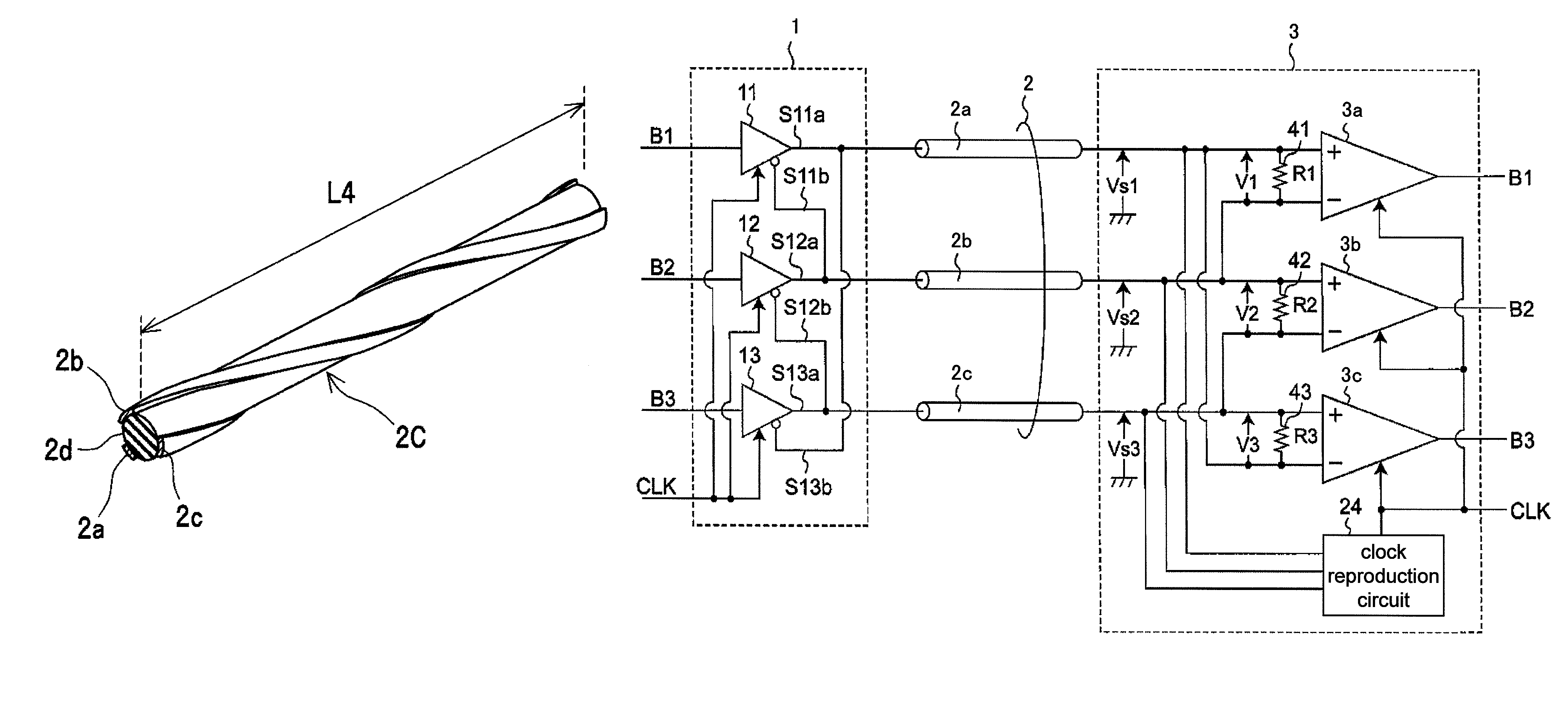
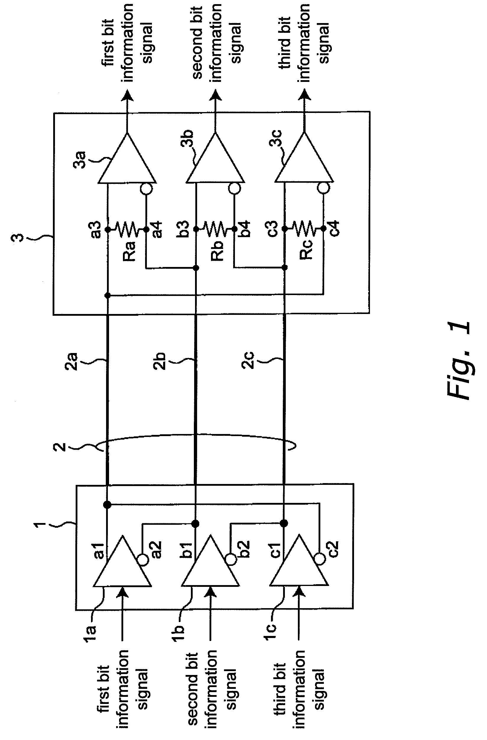
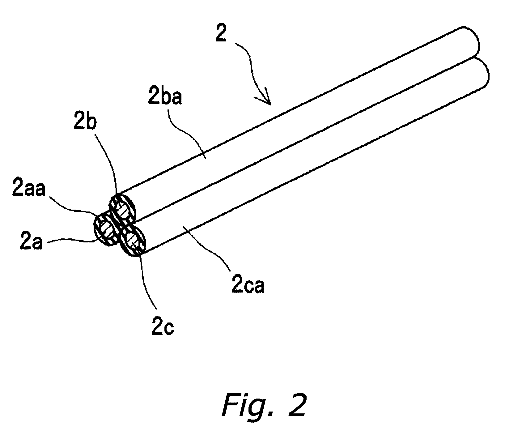
[0060]FIG. 1 is a circuit diagram of a differential transmission circuit according to a first embodiment of the invention, FIG. 2 is a perspective view showing a partial section of the configuration of the differential transmission cable 2 of FIG. 1, and FIG. 3 is a horizontal cross section of the differential transmission cable 2 of FIG. 1. With the differential transmission circuit of this embodiment, three bit information signals are differentially signaled by LVDS via the differential transmission cable 2, which is made from three signal lines 2a, 2b, and 2c.

[0061]In FIG. 1, the differential driver IC1 and the differential receiver IC3 are connected by the differential transmission cable 2, which is made from the three signal lines 2a, 2b, and 2c and serves as the differential transmission line, and the three bit information signals that are input to the differential driver IC1 are transmitted to the differential receiver IC3 via the differential transmission cable 2 and ...

modified example

[0116]FIG. 24 is a flowchart that illustrates this example of the bit information determination process that is executed by the decoding device 50 of the signal receiver 3B in a multiple differential transmission system according to a modified example of the third multiple differential transmission system (using the configuration of FIG. 20, differing only in the setting conditions). Here, the structural configuration of the multiple differential transmission system of FIG. 20 is used. The bit information determination process of FIG. 24 differs from the bit information determination process of FIG. 21 only in that the processing of step S13 has been switched with the processing of step S14. This multiple differential transmission system according to a modified example of the third multiple differential transmission system with this configuration has the same actions and effects as the multiple differential transmission system according to the modified example of the second multiple...

second embodiment

[0119]FIG. 5 is a perspective view showing a partial section of the structure of a differential transmission cable 2B according to a second embodiment of the invention, and FIG. 6 is a horizontal cross section of the differential transmission cable 2B of FIG. 5. Looking at FIGS. 5 and 6, we see that signal lines 2a, 2b, and 2c, which are made of conductors with a predetermined width, are formed on the surface of a dielectric core line 2d, which is formed by a dielectric such as glass epoxy, in the longitudinal direction of the dielectric core line 2d. Like in the case of the first embodiment, the signal lines 2a, 2b, and 2c are disposed such that, when looking at them in horizontal section, the distance L1 between the centers O1 and O2 of the signal lines 2a and 2b, the distance L2 between the centers O2 and O3 of the signal lines 2b and 2c, and the distance L3 between the centers O3 and O1 of the signal lines 2c and 2a, are equal to one another. Thus, the distance between any pair ...


PUM

PropertyMeasurementUnit
voltageaaaaaaaaaa
currentaaaaaaaaaa
impedanceaaaaaaaaaa

Abstract

A transmission cable that has three signal lines, and in which there is little unwanted radiation noise, is provided. In a section that is perpendicular to the longitudinal direction of the differential transmission cable, the distance between any two signal lines of the three signal lines is equal to a predetermined value. The differential transmission cable is twisted in its longitudinal direction. The differential transmission cable further includes a dielectric core line, and the signal lines are formed on the surface of the dielectric core line. In the differential transmission cable, the signal lines are formed in a helix in the longitudinal direction of the dielectric core line.

Description

BACKGROUND OF THE INVENTION[0001]1. Field of the Invention[0002]The present invention relates to transmission cables for transmitting a plurality of signals, and in particular, relates to transmission cables for performing multiple differential transmission in which a plurality of data bits is achieved through differential transmission, which is one method of high-speed signal transmission, with a differential transmission line that is provided with a small number of signal lines.[0003]2. Description of the Related Art[0004]Single-end signals that oscillate with a logical amplitude at the power source voltage have conventionally been used for the transmission of high-speed signals, but the use of low voltage differential signaling (LVDS) has been on the rise in light of the increase in the number of drive frequencies and larger bus widths in conjunction with the recent demand for high-speed data transmission, as well as because of its inhibition of unwanted radiation noise and resis...

Claims


Application Information

Patent Timeline
Patent Type & Authority Patents(United States)
IPC IPC(8): H01B5/16H04B3/00
CPCH04B3/30H04L25/0272H01B11/00
Inventor MATSUBARA, RYOFUSAYASU, HIROTSUGUTANIMOTO, SHINICHIHAMADA, SEIJI
Owner PANASONIC CORP
Why Eureka
Try Eureka