Differential transmission line

a transmission line and differential technology, applied in the field of differential transmission lines, can solve the problems of increasing the wiring region of the printed circuit board, affecting the transmission speed of the signal line, so as to achieve the effect of reducing the noise of unwanted radiation

Inactive Publication Date: 2010-06-22
PANASONIC CORP
View PDF5 Cites 17 Cited by
  • Summary
  • Abstract
  • Description
  • Claims
  • Application Information

AI Technical Summary

Benefits of technology

[0059]According to the invention, in a differential transmission line that has three or more signal lines, the signal lines are formed such that they are equal in length to one another in the signal line route length adjustment segment on the driver unit side, and thus it is possible to provide a differential transmission line in which there is little unwanted radiation noise.

Problems solved by technology

However, compared to ordinary single-end transmission, the differential transmission line of FIGS. 30 and 31 has the numerous above-described merits for high-speed transmission, but requires the two signal lines 912a and 912b in order to transmit a single data bit, and this leads to problems such as requiring a large number of signal lines in order to achieve multiple bit transmission and an increase in the wiring region on the printed circuit board 914.
This created a new problem in that the difference in the signal line route length does not allow the balance between the signal lines to be maintained, and thus their electromagnetic fields cannot cancel each other out and as a result unwanted radiation noise cannot be reduced.

Method used


Image

  • Differential transmission line
  • Differential transmission line
  • Differential transmission line

Examples


first embodiment

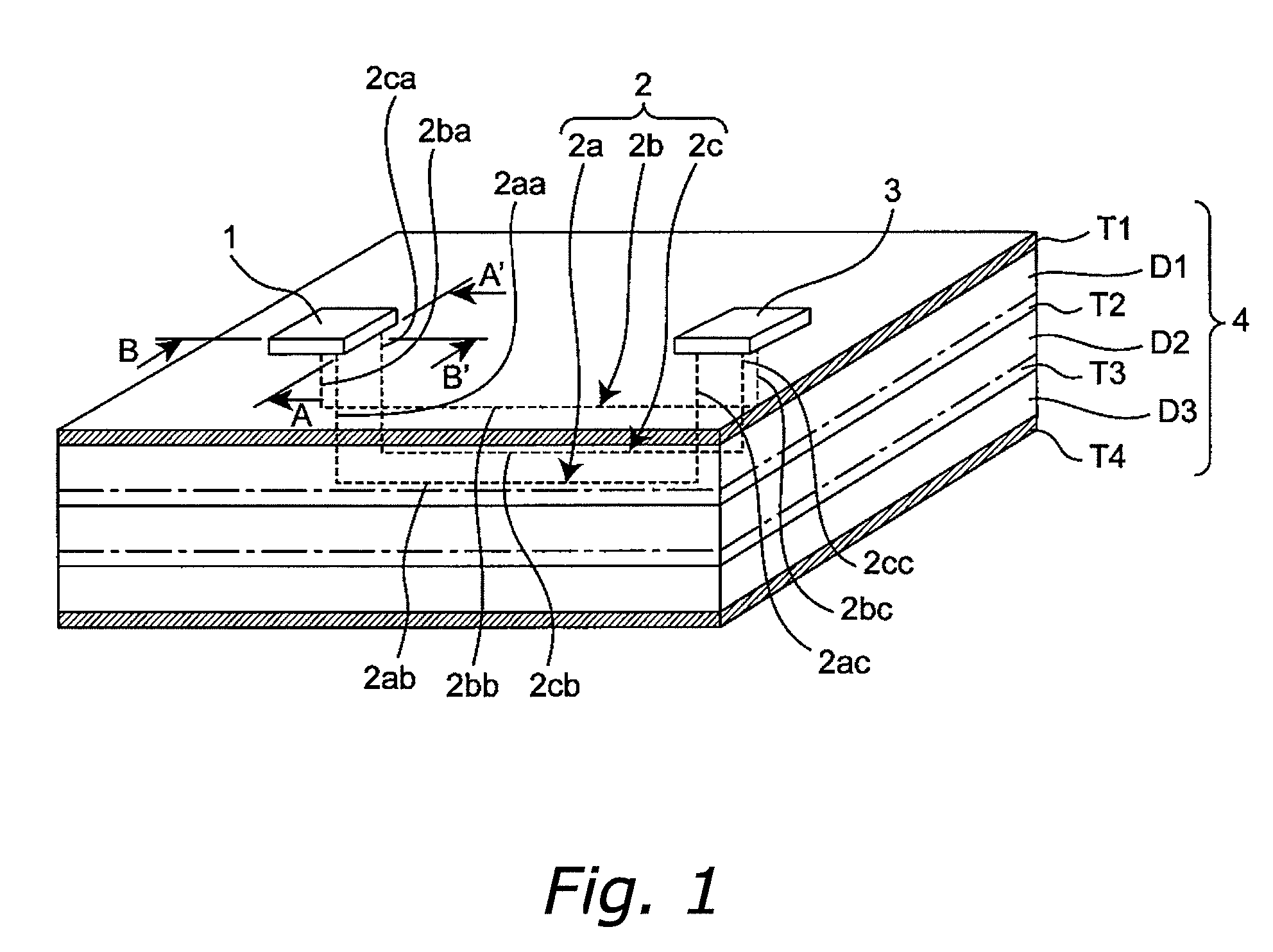
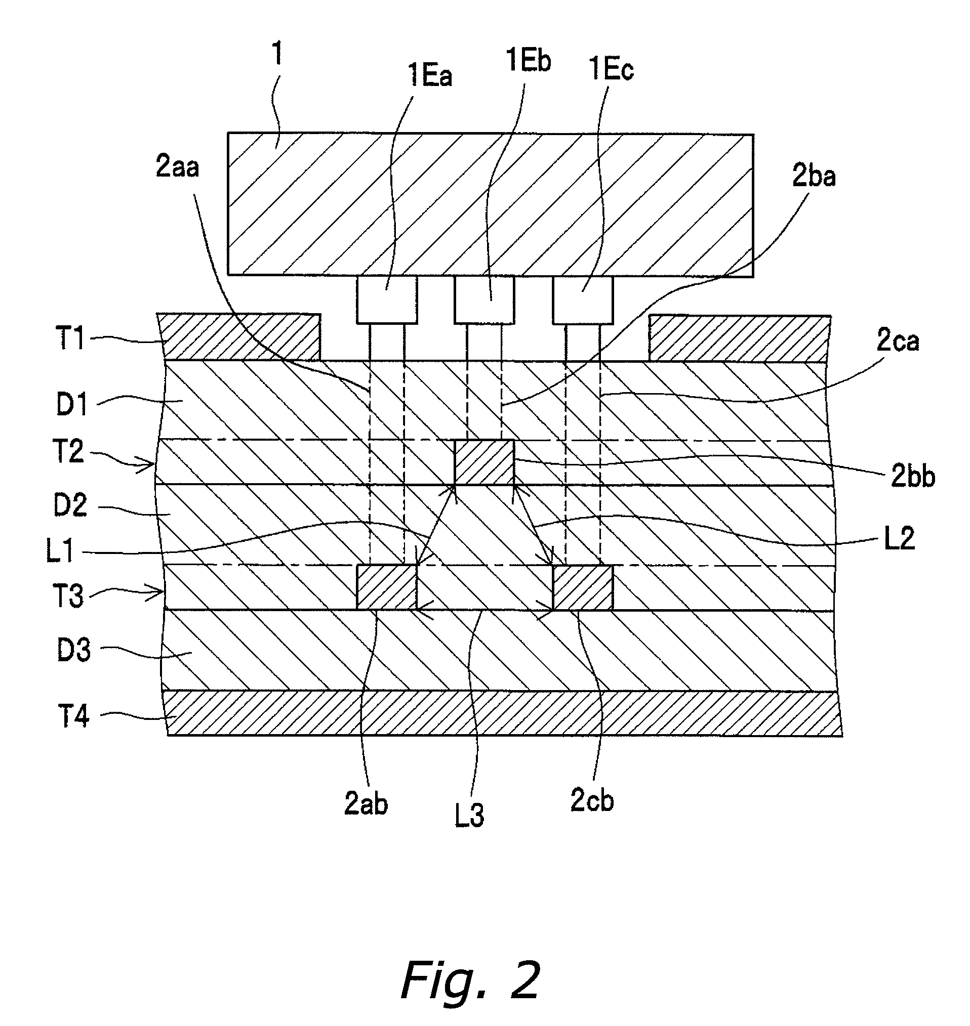
[0094]FIG. 1 is a perspective view that shows the schematic configuration of the differential transmission circuit, with some parts transparent, according to a first embodiment of the invention, FIG. 2 is a cross-sectional view showing the section taken vertically along the line A-A′ in FIG. 1, viewed in the arrow direction, and FIG. 3 is a cross-sectional view showing the section taken vertically along the line B-B′ in FIG. 1, viewed in the arrow direction. The differential transmission line of this embodiment is a differential transmission line 2 that is provided on a printed circuit board 4, which is provided with a plurality of laminated conductor layers T1, T2, T3, and T4, and is provided with three signal lines 2a, 2b, and 2c that transmit differential signals from a differential driver IC 1 on the printed circuit board 4 to a differential receiver IC3 on the printed circuit board 4, and is characterized in that the largest portion of the signal lines 2a, 2b, and 2c resides in...

second embodiment

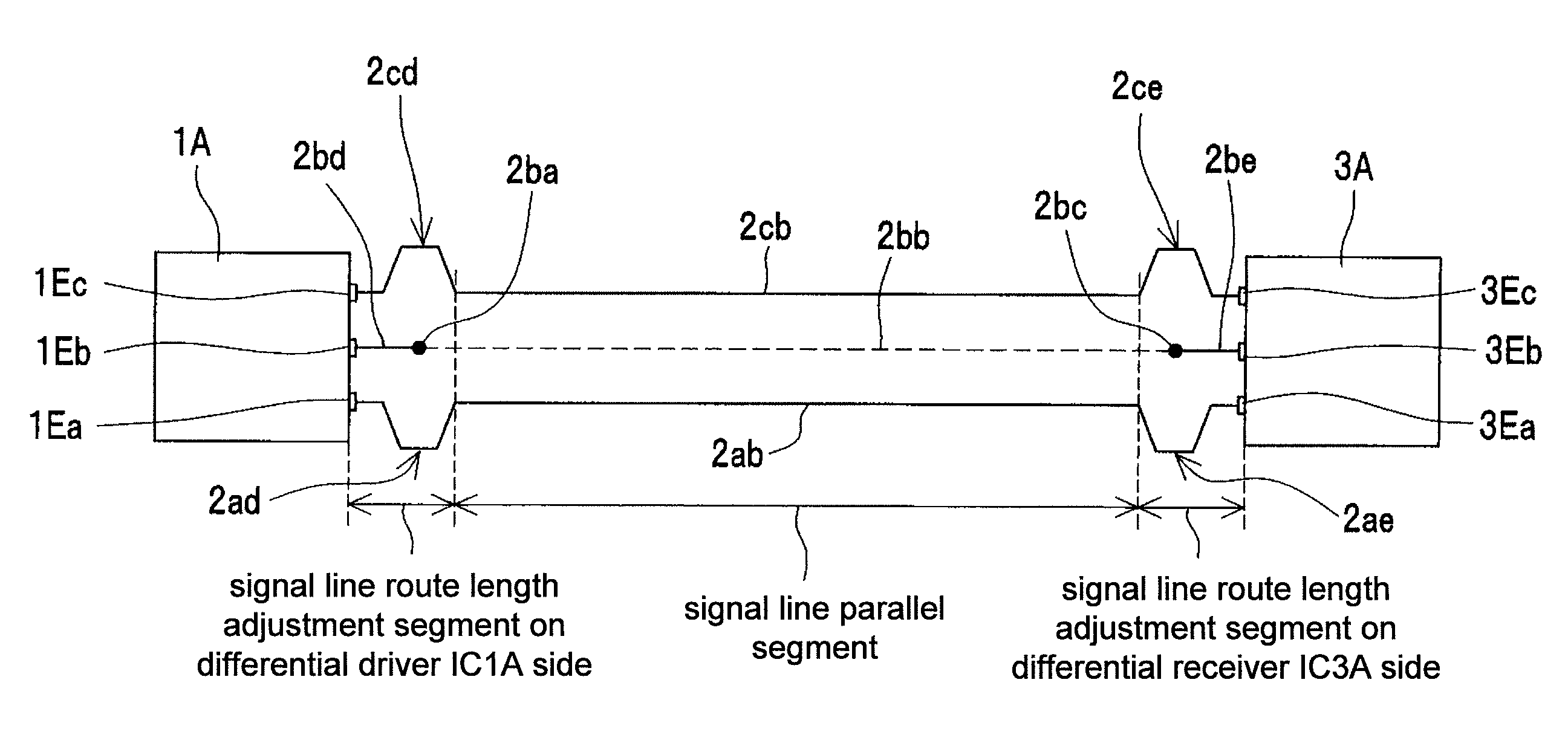
[0162]FIG. 5 is a perspective view that shows the schematic configuration of a differential transmission circuit, with some parts transparent, according to a second embodiment of the invention, and FIG. 6 is a top view of the differential transmission circuit of FIG. 5. In this embodiment, in order to form the signal lines 2a, 2b, and 2c at equal lengths in the signal line route length adjustment segment on the differential driver IC1A side, the signal line route length adjustment segments of signal lines 2a and 2c are provided with signal line return portions 2ad, 2ae, 2cd, and 2ce, instead of adjusting the positions of the differential signal output terminals 1Ea, 1Eb, and 1Ec of the differential driver IC1 as in the first embodiment.

[0163]The differential transmission circuit of this embodiment is provided in a double-sided printed circuit board 4A, which is provided with two conductor layers T5 and T6 and a dielectric layer D4 between these layers. L13 is the distance between th...

third embodiment

[0171]FIG. 7 is a perspective view that shows the schematic configuration of a differential transmission circuit, with some parts transparent, according to a third embodiment of the invention, and FIG. 8 is a cross-sectional view showing the section cut along the line A-A′ in FIG. 7. With the differential transmission circuit of this embodiment, three bit information signals are transmitted via a differential transmission line 2 that is made from three signal lines 2a, 2b, and 2c. It is characterized in that the three signal lines 2a, 2b, and 2c are disposed parallel to one another, and in a section perpendicular to the longitudinal direction of the differential transmission line 2, the three signal lines 2a, 2b, and 2c are disposed at substantially the same spacing on a same circumference, and thus they are located at the apexes of an equilateral triangle. Moreover, in the section perpendicular to the longitudinal direction of the differential transmission line 2, the signal lines ...


PUM


Abstract

A differential transmission line that has three or more signal lines and with which there is little unwanted radiation noise is provided. The differential transmission line 2 is provided with three signal lines 2a, 2b, and 2c that transmit differential signals from a differential driver IC1 to a differential receiver IC3, and the majority of the signal lines 2a, 2b, and 2c is provided in conductor layers T2 and T3 of a printed circuit board 4. The signal lines 2a, 2b, and 2c are provided with a signal line parallel segment, a signal line route length adjustment segment that is on the differential driver IC1 side and that connects from differential signal output terminals 1Ea, 1Eb, and 1Ec in the differential driver IC1 to the signal line parallel segment, and a signal line route length adjustment segment that is on the differential receiver IC3 side and that connects from the signal line parallel segment to differential signal input terminals in the differential receiver IC3, wherein the signal lines 2a, 2b, and 2c are formed such that their signal line route length adjustment segments on the differential driver IC1 side are equal in length to one another.

Description

BACKGROUND OF THE INVENTION[0001]1. Field of the Invention[0002]The present invention relates to differential transmission lines for transmitting signals at high speeds via a cable or the wiring pattern on a printed circuit board, for example, and in particular, relates to differential transmission lines adapted for issues with electro magnetic compatibility (hereinafter EMC) for preventing unwanted radiation noise from occurring.[0003]2. Description of the Related Art[0004]Single-end signals that oscillate with a logical amplitude at the power source voltage have conventionally been used for the transmission of high-speed signals, but the use of low voltage differential signaling (LVDS) has been on the rise in light of the increase in the number of drive frequencies and larger bus widths in conjunction with the recent demand for high-speed data transmission, as well as because of its inhibition of unwanted radiation noise and resistance against exogenous noise. With LVDS, generally...

Claims


Application Information

Patent Timeline
Patent Type & Authority Patents(United States)
IPC IPC(8): H03K19/094H03K19/0175
CPCH04B3/34H04L25/0272H05K1/0245H05K1/0248H05K1/0298H01L2224/49175H05K2201/09672H01L2924/3011H05K2201/09236H01L2224/48137H01L2924/00
Inventor FUSAYASU, HIROTSUGUHAMADA, SEIJITANIMOTO, SHINICHIMATSUBARA, RYO
Owner PANASONIC CORP
Why Eureka
Try Eureka