Switching system and method for communicating information at a customer premises

a switching system and customer technology, applied in the field of communication, can solve the problems of scaling, ongoing maintenance costs, and inability to provide voice, video, data and other services in an integrated manner using a system having relatively low implementation, and achieve the effect of substantially reducing the disadvantages and problems of previous switching systems and methods

Inactive Publication Date: 2011-10-18
INTEL CORP
View PDF42 Cites 0 Cited by
  • Summary
  • Abstract
  • Description
  • Claims
  • Application Information

AI Technical Summary

Benefits of technology

[0008]According to the present invention, disadvantages and problems associated with previous switching systems and methods are substantially reduced or eliminated.
[0011]The present invention provides a number of important technical advantages over previous systems and methods. Unlike previous systems, the switching system of the present invention can be provisioned to include a single logical data link from the switching system to the CO site. This link bidirectionally carries data, packetized voice, packetized video, and any other appropriate packetized information streams. The switching system may provide POTS on multiple subscriber line ports, with built-in facilities to bidirectionally convert between the analog POTS and packetized digital service to and from the CO. It may also provide suitable xDSL service over the POTS that is provided on each subscriber line, with connectivity to an Internet service provider (ISP) for each of the subscriber lines. It may provide a built-in LAN port (based on Ethernet or otherwise) and an associated switching (or routing) bridge to support the creation of a LAN inclusive of the subscriber line data channels and the LAN port. It may provide LAN service even for subscriber data connections using the Point to Point (PPP) protocol. The ability to provide these and other service options to multiple users within a community is an important technical advantage over prior systems.
[0012]Moreover, the switching system of the present invention is “stackable” using interconnecting links that permit multiple smaller devices to operate as if they were a single larger device. The interconnecting “stack links” between devices can be modular and multiprotocol. These features contribute to the enhanced scalability of the system and may allow for economical incremental expansion beginning with a low cost of entry version with a low port count. The switching system is more manageable than prior systems, permitting both local and remote configuration and monitoring. It may support single or multiple physical links to one or more COs, providing data link fault tolerant operation, higher bandwidth, and other important technical advantages. It may also provide for distributed Inverse Multiplex ATM (IMA) operation using these CO links. The present invention allows various combinations of these and other services to be provided at lower total cost than with multiple overlapping systems to provide such services piecemeal.

Problems solved by technology

As a result, communities requiring such services have usually faced relatively large initial expenses for implementing a system, subsequently increasing system capacity, and maintaining the system on an ongoing basis.
Attempts to integrate such services to offset these inadequacies have typically forced users in these communities to accept a number of undesirable limitations, for example, limitations as to the generality of data services available.
Previous systems do not provide voice, video, data, and other services in an integrated manner using a system having relatively low implementation, scaling, and ongoing maintenance costs.
As a result of these and other inadequacies, previous systems are often inadequate to address the current and future needs of many user communities.

Method used


Image

  • Switching system and method for communicating information at a customer premises
  • Switching system and method for communicating information at a customer premises
  • Switching system and method for communicating information at a customer premises

Examples


Embodiment Construction

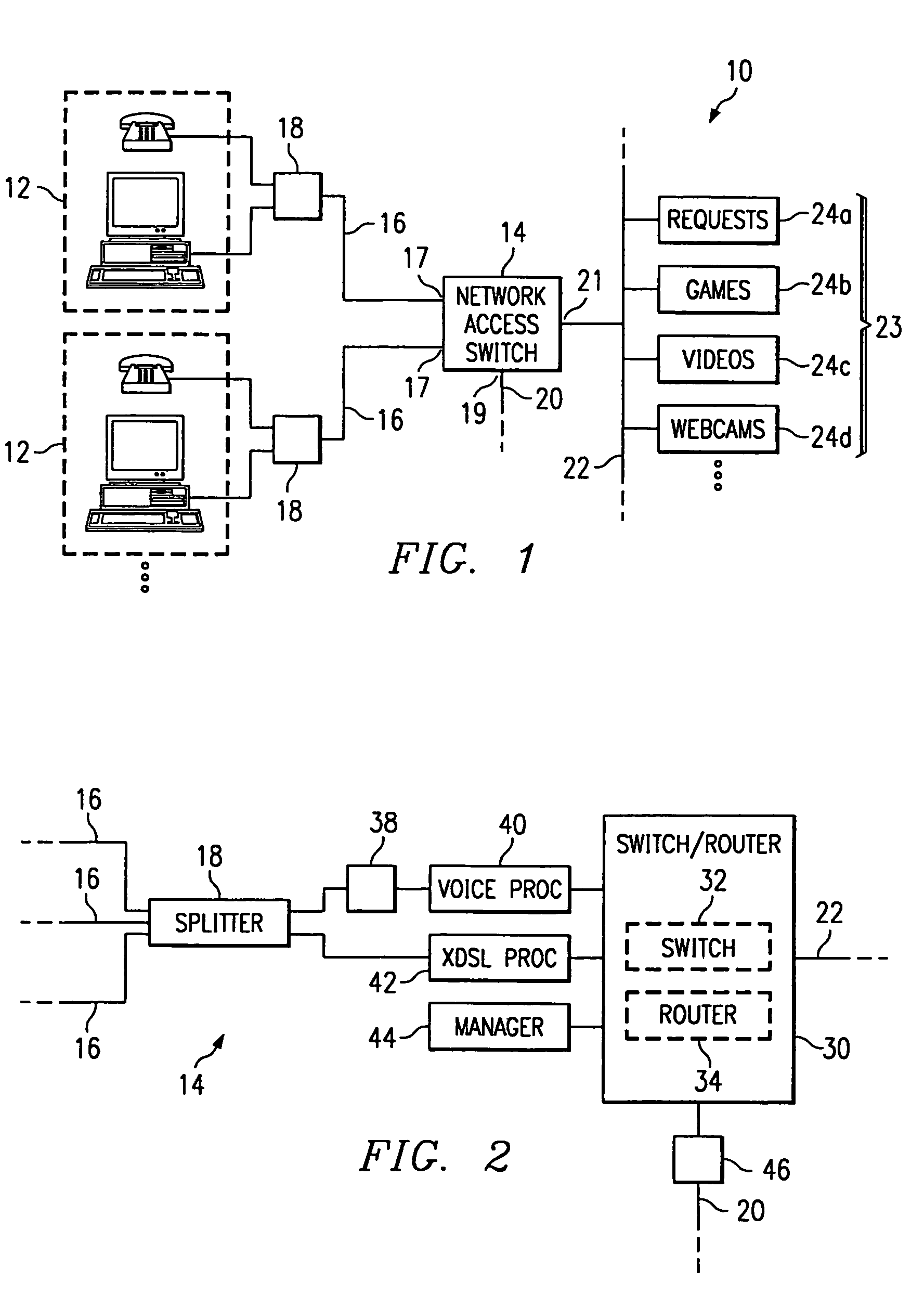
[0025]FIG. 1 illustrates an exemplary system 10 for communicating information in a subscriber community to provide integrated audio, video, data, and other appropriate services to subscribers. The subscriber community may include a business, apartment complex, retirement community, correctional facility, or any other customer premises in which subscribers share communications infrastructure and resources. Each subscriber in the served community has one or more associated telephones, personal computers, facsimile machines, or other devices to interface with the public switched telephone network (PSTN) or other telephone network, a local area network (LAN), metropolitan area network (MAN), wide area network (WAN), a global network such as the Internet, or any other suitable networks. Such devices may be referred to collectively, where appropriate, as subscriber devices 12. Network access switch 14 is coupled to subscriber devices 12 using subscriber lines 16 (and their subscriber line...


PUM


Abstract

A switching system (14) at a customer premises communicates information associated with one or more subscribers. The switching system (14) includes multiple subscriber line ports (17) for communicating xDSL signals with subscribers, the xDSL signals containing both data signals and POTS voice signals. A logical port (20) communicates data signals and packetized voice signals from the subscribers with a central office, the switching system (14) converting between the POTS voice signals of the subscriber lines (16) and the packetized voice signals of the logical port (20). A LAN port (21) communicates data signals with a server complex (23) using a LAN (22) to provide data services to the subscribers. The switching system (14) may include a switch (32) that receives voice signals on a first virtual circuit (VC), switches the voice signals out of the switching system (14) on the first VC, and also communicates received data signals for routing. A router (32) within the switching system (14) may receive the data signals from the switch (32) on a second VC, determine a third VC for the data signals, and route the data signals to the switch (32) on the third VC for communication out of the switching system (14) on the third VC.

Description

RELATED APPLICATIONS[0001]This application claims the benefit of U.S. Provisional Patent Application No. 60 / 204,898, filed on May 17, 2000 and is a continuation of U.S. application Ser. No. 09 / 662,733, filed Sep. 15, 2000 now U.S. Pat. No. 6,775,271.[0002]This application is related to:[0003]U.S. application Ser. No. 09 / 663,391, filed Sep. 15, 2000 by Brian W. Johnson, K. Arlan Harris, and Manlio D. Marquez, for a System and Method for Prioritizing and Communicating Subscriber Voice and Data Information; and[0004]U.S. application Ser. No. 09 / 662,734, filed Sep. 15, 2000 by Brian W. Johnson, for a System and Method for Communicating Information Using Inverse Multiplex ATM (IMA) Functionality.TECHNICAL FIELD OF THE INVENTION[0005]This invention relates in general to the field of communications and in particular to a switching system and method for communicating information at a customer premises.BACKGROUND OF THE INVENTION[0006]Historically, voice, video, data, and other services have...

Claims


Application Information

Patent Timeline
Patent Type & Authority Patents(United States)
IPC IPC(8): H04L12/28H04L12/66
CPCH04M3/007
Inventor JOHNSON, BRIAN W.HARRIS, K. ARLANGEIGER, GREGORY E.
Owner INTEL CORP
Why Eureka
Try Eureka