Magnetically actuated auto-closing air vent

a technology of magnetically driven and air vents, which is applied in the field of air vents, can solve the problems of degrading the functioning of critical mechanical devices, and achieve the effect of preventing the spread of fire and minimizing the movement of parts

Inactive Publication Date: 2011-11-22
CARLSON THOMAS R +2
View PDF9 Cites 42 Cited by
  • Summary
  • Abstract
  • Description
  • Claims
  • Application Information

AI Technical Summary

Benefits of technology

[0018]In an alternative embodiment of the present invention, a helical compression spring may be disposed between the damper and the vent housing to provide mechanical redundancy in driving the damper closed. While not necessary for activation of the unit, such a feature may be prudent as a safety backup.
[0019]When placed in an outside wall or soffit, the damper in the auto-closing vent of the present invention closes from front to back. Thus, in addition to minimizing moving parts, the present invention uses drafts caused by an outside fire to assist in closing the damper. The auto-closing vent is adapted for use not only on fire-resistant buildings, such as one those with non-flammable exteriors, but conventional wood sided buildings as well. Importantly, the vent will retard entry of the fire for a critical period at the onset of the fire, and may thus provide more time for firefighters to save property and lives.
[0023]It is yet another object of the present invention to provide a self-closing vent that minimizes moving parts that may fail when exposed to high temperatures.
[0024]From the foregoing, it will be appreciated that another principal object of the present invention is to provide an apparatus that prevents or retards the distribution of fire gases in a ventilating system.
[0025]Still another object of the present invention is to prevent the spread of fire itself.

Problems solved by technology

However, vents are routinely installed in places exposed to moisture, and the resulting corrosion degrades the functioning of critical mechanical devices.

Method used


Image

  • Magnetically actuated auto-closing air vent
  • Magnetically actuated auto-closing air vent
  • Magnetically actuated auto-closing air vent

Examples


Embodiment Construction

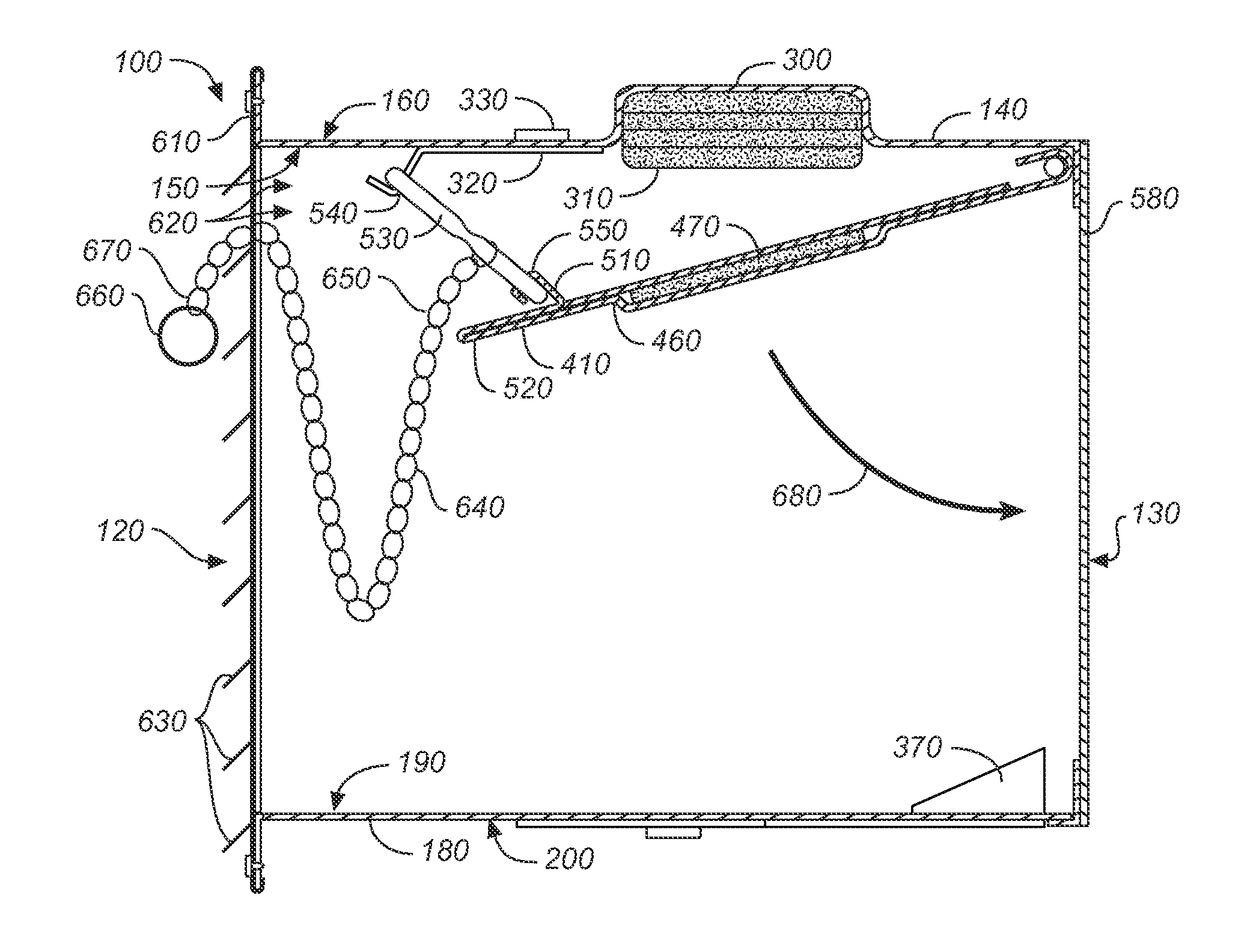
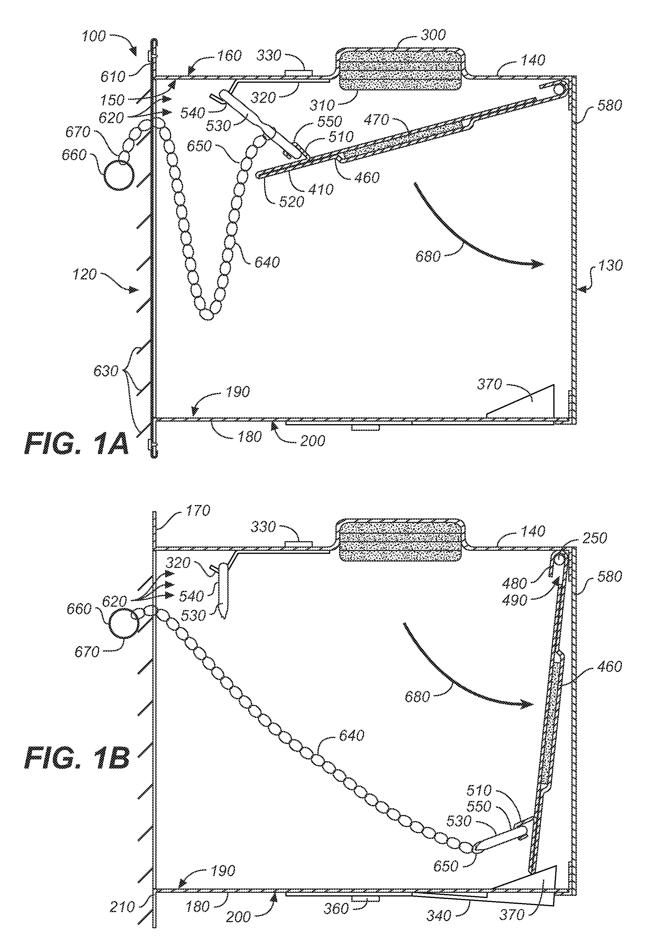
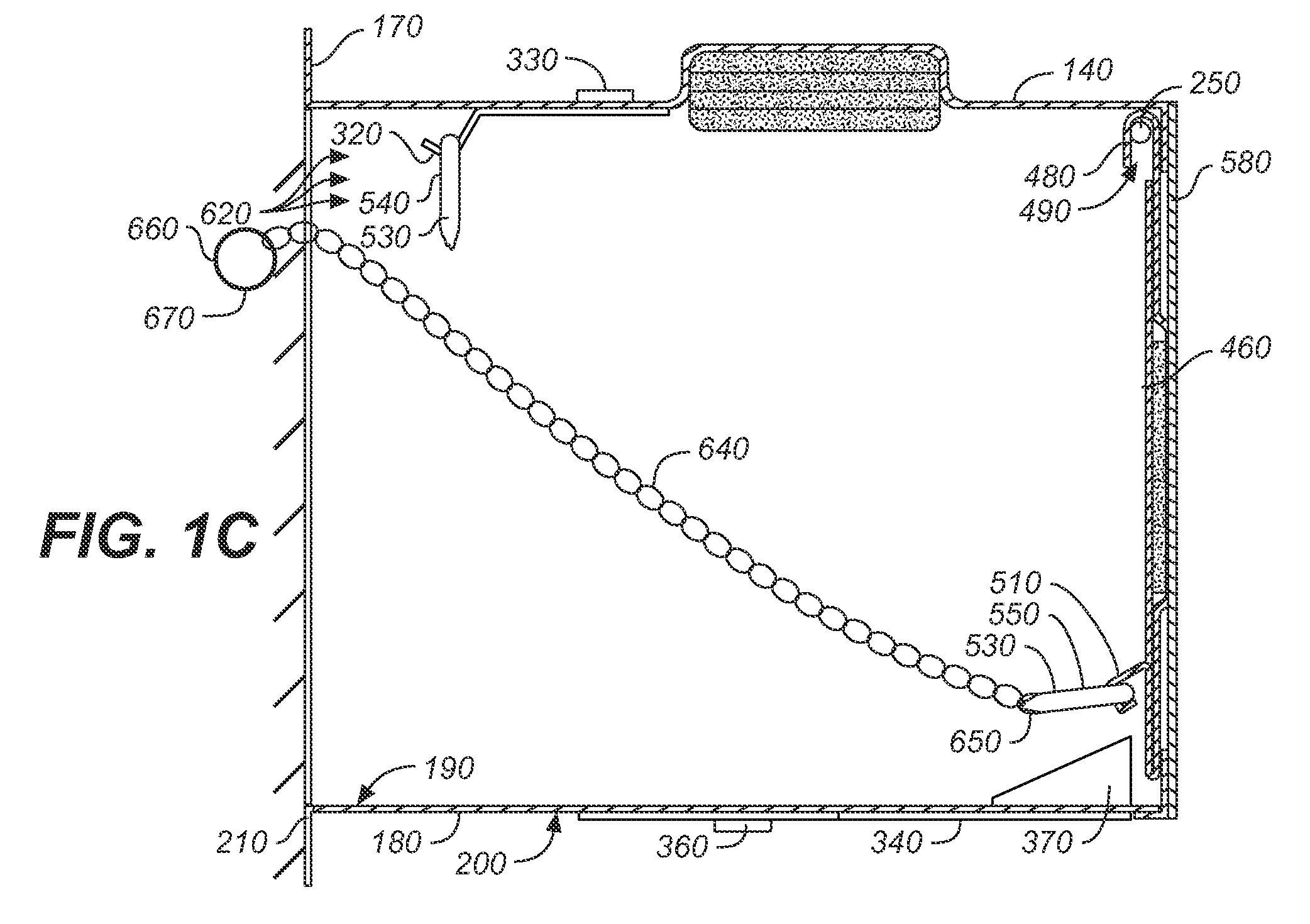
[0040]Referring to FIGS. 1 through 6, wherein like reference numerals refer to like components in the various views, there is illustrated therein a new and improved magnetically actuated auto-closing vent, generally denominated 100 herein. Collectively, these views show that the inventive auto-closing vent includes a box-like vent housing 110 comprising: a generally open front 120; a generally open rear 130; a top panel 140 having an interior side 150, an exterior side 160, and a top mounting flange 170; a bottom panel 180 having an interior side 190 an exterior side 200 and a bottom mounting flange 210; a right side panel 220 adjoining and connecting each of the top and bottom panels and having a side mounting flange 230, and a threaded hinge pin hole 240 proximate the upper right rear corner through which a threaded right hinge pin (e.g., a sheet metal screw) 250 is threadably inserted; and a left side panel 260 adjoining and connecting each of the top and bottom panels and having...


PUM


Abstract

A self-closing vent intended for use in attics, crawl spaces, joist cavities, exterior walls, interior walls, or other structural element which allows for the free flow of air from outside a building to interior spaces during normal use. The vent includes a damper blade pivotally connected to, and disposed within, the vent housing, which is held in an open position by a temperature sensitive fusible link. Two, and preferably three, permanent magnets provide the force for driving the damper blade into a closed and locked position. A first magnet disposed in a side of the vent housing and a second magnet disposed on the damper blade are disposed with opposing (repelling) polarities when the damper blade is held in the open position. A third magnet disposed proximate the back of the vent housing is oriented so as to attract the magnet disposed on the damper blade. Thus, when the fusible link is broken by high temperatures, the first magnet propels the damper blade toward the closed position, and the third magnet attracts the damper blade to assist in putting it into a fully closed position. The third magnet and second magnet then cooperate to effect a secure closure, which is supplemented by mechanical locks disposed in the vent housing.

Description

CROSS REFERENCES TO RELATED APPLICATIONS[0001]The present application claims the benefit of U.S. Provisional Patent Application Ser. No. 60 / 910,142, filed Apr. 4, 2007, (Apr. 4, 2007).STATEMENT REGARDING FEDERALLY SPONSORED RESEARCH OR DEVELOPMENT[0002]Not applicable.THE NAMES OR PARTIES TO A JOINT RESEARCH AGREEMENT[0003]Not applicable.INCORPORATION-BY-REFERENCE OF MATERIAL SUBMITTED ON A COMPACT DISC[0004]Not applicable.BACKGROUND OF THE INVENTION[0005]1. Field of the Invention[0006]The present invention relates generally to air vents used in building structures, and more particularly to air vents having automatic damper operation apparatus, and still more particularly to a fire safety magnetically driven auto-closing vent for soffits and walls that connect the exterior of a building to its interior or that connect adjoining rooms in a building. The inventive apparatus prevents the rapid ingress of fire and fire gasses in buildings through the vents of a ventilating system.[0007]2...

Claims


Application Information

Patent Timeline
Patent Type & Authority Patents(United States)
IPC IPC(8): A62C2/12F24F11/76
CPCA62C2/12A62C2/242Y10T137/1963F24F2011/0098Y10S454/904F24F2013/148F24F11/35
Inventor CARLSON, THOMAS R.MARUSIC, RADOS R.CARLSON-MARUSIC, THERESA
Owner CARLSON THOMAS R
Why Eureka
Try Eureka