Bridge span and bridge span transportation vehicle

a technology of transportation vehicle and bridge span, which is applied in the direction of bridge type, vessel construction, propulsive elements, etc., can solve the problems that floating bridges cannot be used for crossing dry gaps, and the known system is not suitable for wet gaps

Active Publication Date: 2012-01-17
CONSTR NAVALES & IND DE LA MEDITERRANEE CNIM
View PDF20 Cites 6 Cited by
  • Summary
  • Abstract
  • Description
  • Claims
  • Application Information

AI Technical Summary

Benefits of technology

[0005]The present invention aims to eliminate the disadvantages above by proposing a system for transport of at least one span by an amphibious road vehicle so that it is used either for laying the span over a dry gap, or as a floating ferry or bridge for crossing a wet gap regardless of the width of the latter.
[0007]The amphibious vehicle is preferably provided with one or more inflatable lateral ballasts, of the tubular type, making it possible to increase the floatability and stability of the amphibious vehicle.
[0009]The span extends longitudinally with respect to the transport vehicle and comprises two twinned parallel, roughly parallelepiped boxes defining two upper tracks and two ramps for access to the tracks, which are respectively articulated to the two ends of the boxes around a transverse pin, and a means is provided so as to make possible the pivoting of each ramp from an inactive position folded over the corresponding box to an active deployed position in extension of the box in which the access ramp is maintained when the span is used for crossing a dry gap or in which the access ramp can be adjusted to a determined angular position on either side of its position in extension of the box when the vehicle is used as floating ferry in such a way as to adapt the ramp to the profile of the bank of the gap filled with water when the ramp must rest on this bank for the transfer of any vehicle from the bank onto the span or the transfer of the vehicle from the span onto the bank.
[0012]The connecting means makes it possible to connect end-to-end the ends of the two deployed access ramps of a given end of the span of the amphibious vehicle respectively to the ends of the two deployed access ramps of a given end of the span of the other amphibious vehicle.
[0014]According to an embodiment variant, the connecting means makes it possible to connect end-to-end the ends of two access ramps of a given end of the span of the amphibious vehicle and occupying their position folded over the span respectively to the ends of the two access ramps of a given end of the span of the other amphibious vehicle and also occupying their position folded over this span.
[0015]According to yet another embodiment variant, the connecting means makes it possible to connect, by overlapping, the ends of the two deployed access ramps of a given end of the span of the amphibious vehicle to the ends of the two deployed access ramps of a given end of the span of the other amphibious vehicle.

Problems solved by technology

However, these known systems are not suitable for crossing wet gaps, that is to say gaps filled with water, whose width is such that the span cannot cover them.
However, these floating bridges cannot be used for crossing dry gaps.

Method used


Image

  • Bridge span and bridge span transportation vehicle
  • Bridge span and bridge span transportation vehicle
  • Bridge span and bridge span transportation vehicle

Examples


Embodiment Construction

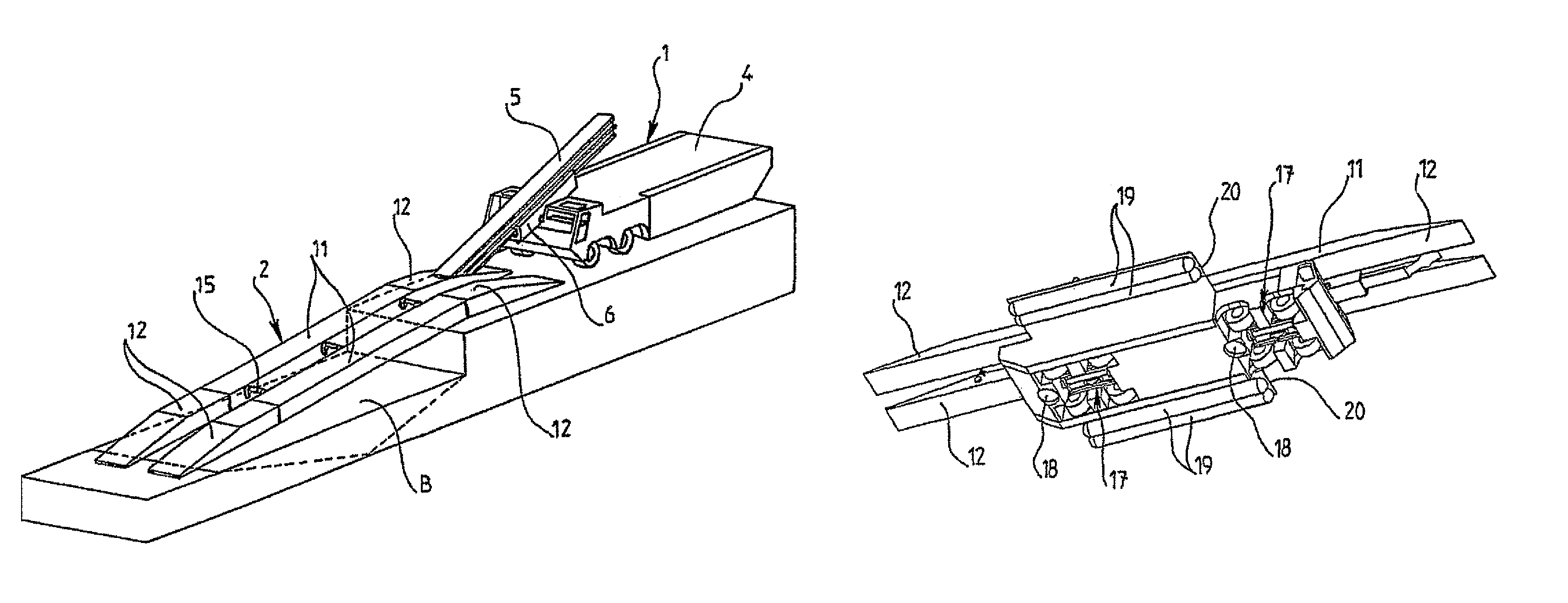
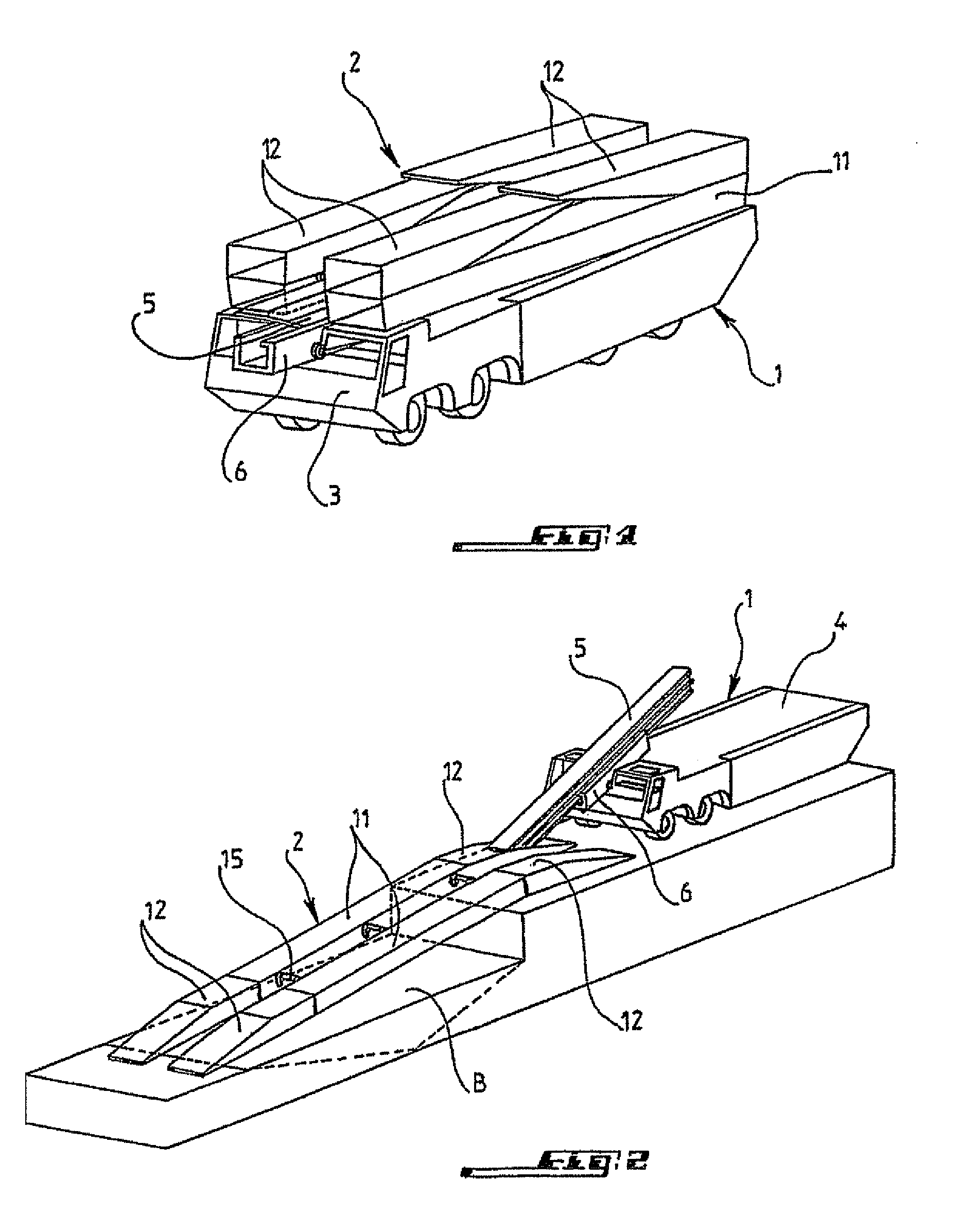
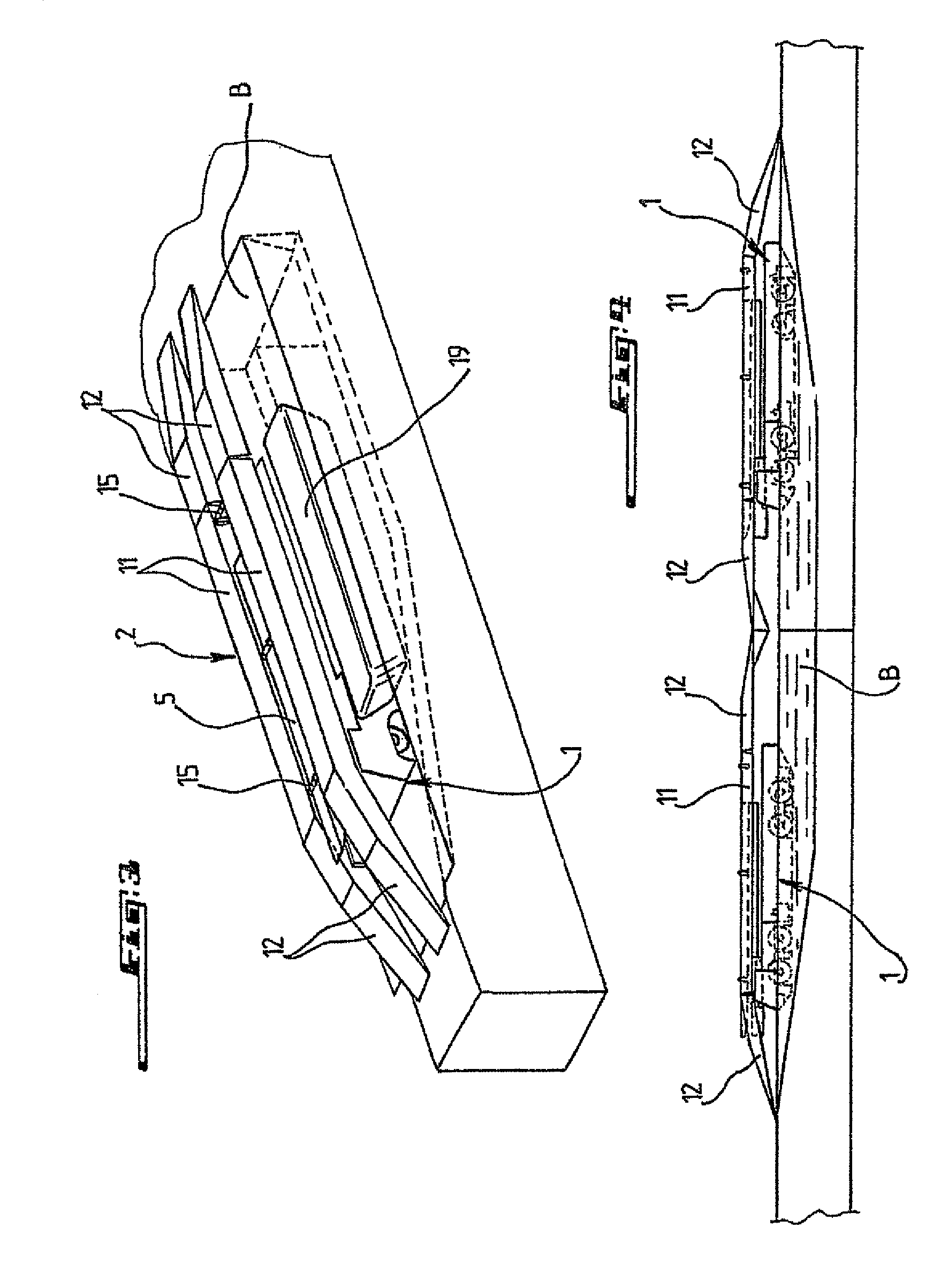
[0039]In reference to FIGS. 1 to 15, reference 1 designates a road vehicle, such as a truck, enabling one to transport span 2 towards a gap that needs to be crossed by vehicles VT, for example, military vehicles.

[0040]Vehicle 1 has armored cab 3 extended in the rear by longitudinal chassis 4 which supports the system for laying span 2 over gap B.

[0041]This system has beam 5 for support and launching of span 2 arranged in resting position on chassis 4 of the vehicle in its longitudinal axis and which can be moved relative to the vehicle according to this axis between its inactive position resting on the vehicle and a launching position projecting with respect to the vehicle.

[0042]Beam 5 is made up of a strong structure with an I-shaped cross section and is mounted on an underframe in the form of girder 6 which can tilt around fixed horizontal pin 7 relative to the chassis of vehicle 1 in order to make possible the tilting of the beam from its horizontal position projecting with respe...


PUM


Abstract

A system for transporting a span on a road vehicle capable of being transformed into an amphibious vehicle, enabling crossing of a dry or water-filled gap by any road vehicle. The vehicle for transporting the span is amphibious to allow any vehicle to cross a gap filled with water by transferring and transporting the vehicle on the span supported on the amphibious vehicle operating as a floating ferry. The invention is particularly applicable in the field of civil or military engineering.

Description

FIELD OF THE INVENTION[0001]The present invention relates to a system for transport of at least one span by a road vehicle and for laying the span from the vehicle over a dry gap in order to enable any road vehicle to cross the dry gap by driving over the span laid over this gap.BACKGROUND[0002]Such systems are known, for example, from French Patent No. 2 666 772 and French Patent No. 2 683 837 in the name of the applicant.[0003]However, these known systems are not suitable for crossing wet gaps, that is to say gaps filled with water, whose width is such that the span cannot cover them.[0004]Also known is the use of modular floating bridges which can be put end-to-end in order to cover all widths of wet gaps and enable them to be crossed by any road vehicle. However, these floating bridges cannot be used for crossing dry gaps.SUMMARY OF THE INVENTION[0005]The present invention aims to eliminate the disadvantages above by proposing a system for transport of at least one span by an am...

Claims


Application Information

Patent Timeline
Patent Type & Authority Patents(United States)
IPC IPC(8): E01D15/127
CPCB60F3/0061E01D15/127E01D15/22
Inventor RICHEUX, ELISABETHAUBERT, HENRI
Owner CONSTR NAVALES & IND DE LA MEDITERRANEE CNIM
Why Eureka
Try Eureka