Light emitting diode illumination system

a technology of light-emitting diodes and illumination systems, which is applied in the direction of lighting and heating apparatus, instruments, lighting support devices, etc., can solve the problems of not describing the light-emitting diodes illumination systems, and achieve the effects of low manufacturing cost, convenient and efficient manufacturing and marketing, and durable and reliable construction

Inactive Publication Date: 2012-01-17
STEPHENS OWEN
View PDF167 Cites 123 Cited by
  • Summary
  • Abstract
  • Description
  • Claims
  • Application Information

AI Technical Summary

Benefits of technology

[0009]To attain this, the present invention essentially comprises a light emitting diode illumination system for utilizing flat thin panels to light up an area in a safe, compact, convenient and economical manner. First provided is an area to be lit up. The area includes a ceiling formed of a grid work of rectangular supports. Each support has a peripheral ledge.
[0021]It is another object of the present invention to provide a new and improved light emitting diode illumination system which may be easily and efficiently manufactured and marketed.
[0022]It is further object of the present invention to provide a new and improved light emitting diode illumination system which is of durable and reliable constructions.
[0023]An even further object of the present invention is to provide a new and improved light emitting diode illumination system which is susceptible of a low cost of manufacture with regard to both materials and labor, and which accordingly is then susceptible of low prices of sale to the consuming public, thereby making such light emitting diode illumination system economically available to the buying public.
[0024]Even still another object of the present invention is to provide a light emitting diode illumination system for utilizing flat thin panels to light up an area in a safe, compact, convenient and economical manner.

Problems solved by technology

While the prior art devices fulfill their respective, particular objectives and requirements, they do not describe a light emitting diode illumination system that allows for utilizing flat thin panels to light up an area in a safe, compact, convenient and economical manner.

Method used


Image

  • Light emitting diode illumination system
  • Light emitting diode illumination system
  • Light emitting diode illumination system

Examples


Embodiment Construction

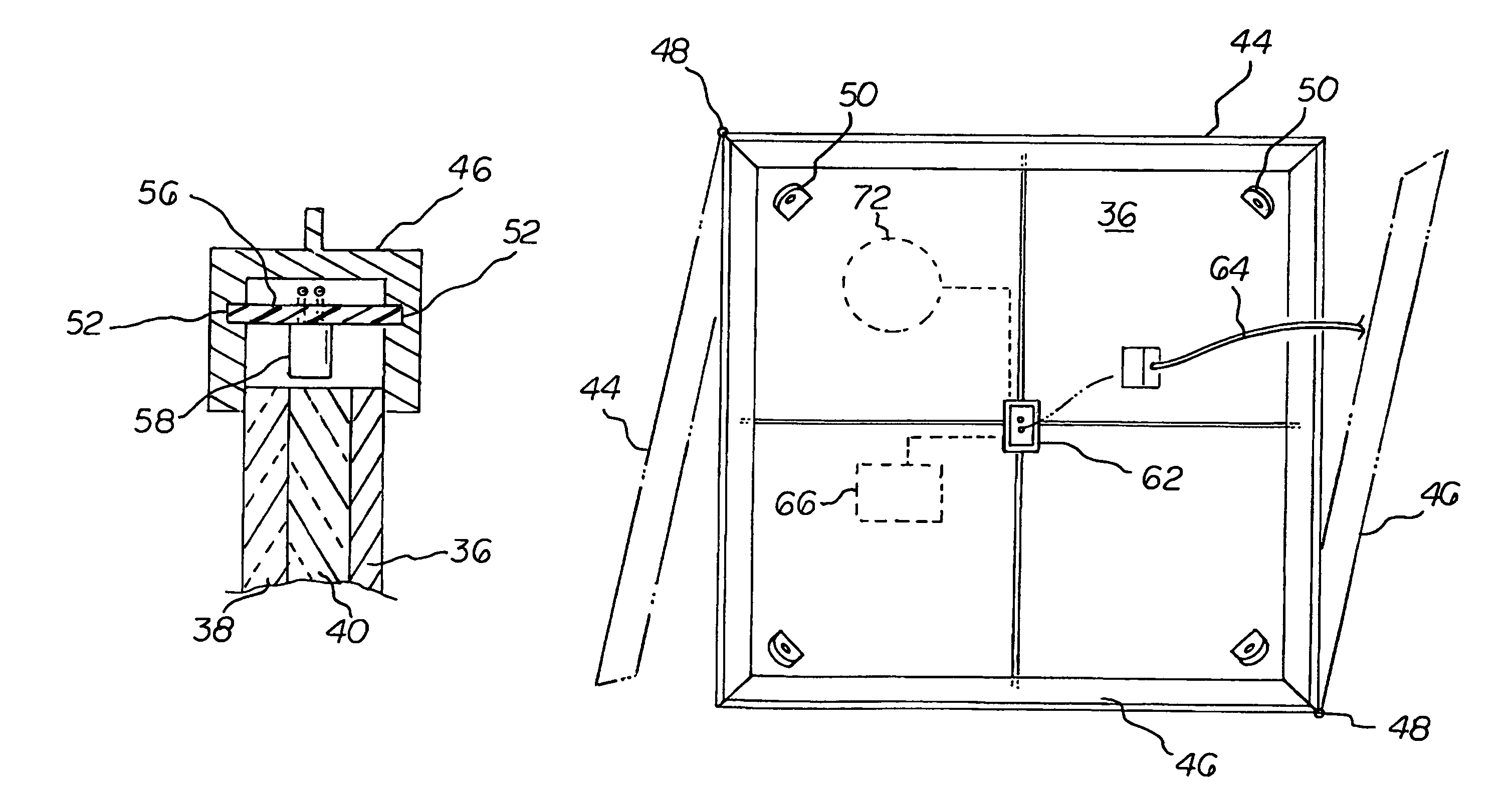
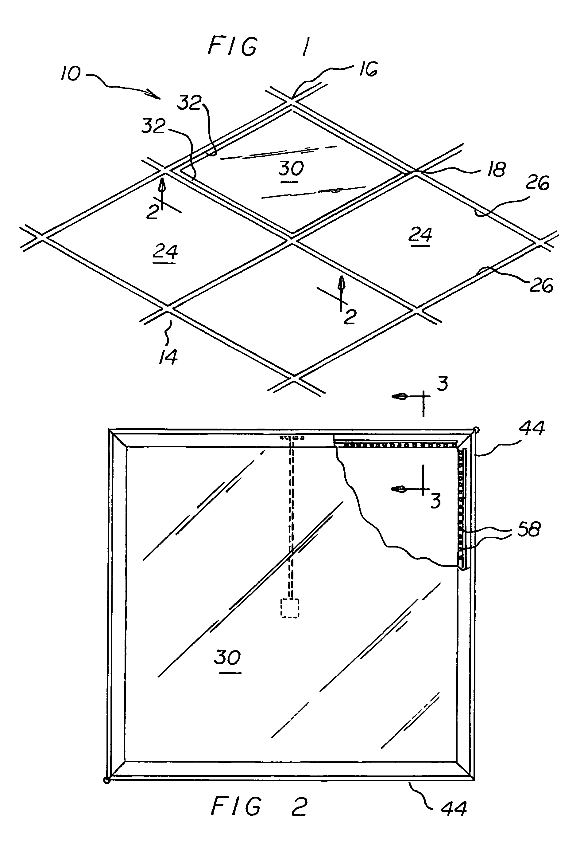
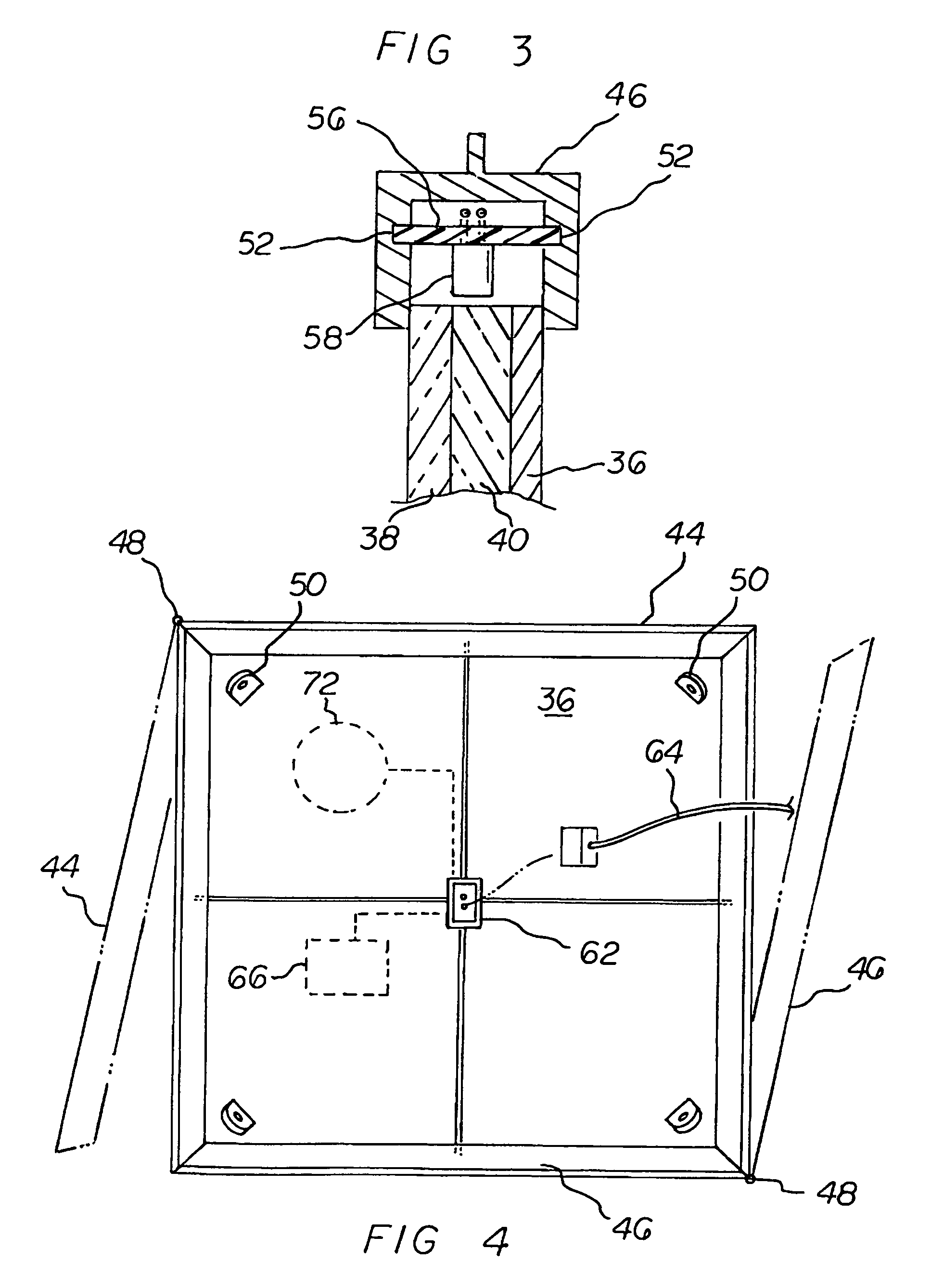
[0035]With reference now to the drawings, and in particular to FIG. 1 thereof, the preferred embodiment of the new and improved light emitting diode illumination system embodying the principles and concepts of the present invention and generally designated by the reference numeral 10 will be described.

[0036]The present invention, the light emitting diode illumination system 10 is comprised of a plurality of components. Such components in their broadest context include an illumination panel, a printed circuit board and an electrical connector. Such components are individually configured and correlated with respect to each other so as to attain the desired objective.

[0037]The light emitting diode illumination system 10 is for utilizing flat thin panels to light up an area in a safe, compact, convenient and economical manner. First provided is an area 14 to be lit up. The area includes a ceiling 16 formed of a grid work of rectangular supports 18. Each support has a peripheral ledge 20...


PUM


Abstract

An illumination panel has four peripheral edges constructed of an upper plate and a lower plate. Each of the plates has aligned peripheral edges and an upper and lower surface. The upper plate is fabricated of an optically reflective material. The lower plate is fabricated of an optically diffusive material. Each of the illumination panels includes a peripheral frame formed of four edge pieces. Each of the edge pieces is in a cross sectional configuration to receive and support the peripheral edges of the plates. A pair of opposed recesses face each other in the edge pieces. A printed circuit board with a plurality of light emitting diodes is supported in the edge pieces by the recesses. An electrical connector is adapted to disperse electrical power to the light emitting diodes.

Description

BACKGROUND OF THE INVENTION[0001]1. Field of the Invention[0002]The present invention relates to a light emitting diode illumination system and more particularly pertains to utilizing flat thin panels to light up an area in a safe, compact, convenient and economical manner.[0003]2. Description of the Prior Art[0004]The use of illumination systems of known designs and configurations is known in the prior art. More specifically, illumination systems of known designs and configurations previously devised and utilized for the purpose of lighting up an area are known to consist basically of familiar, expected, and obvious structural configurations, notwithstanding the myriad of designs encompassed by the crowded prior art which has been developed for the fulfillment of countless objectives and requirements.[0005]While the prior art devices fulfill their respective, particular objectives and requirements, they do not describe a light emitting diode illumination system that allows for util...

Claims


Application Information

Patent Timeline
Patent Type & Authority Patents(United States)
IPC IPC(8): F21S8/00F21V7/04
CPCF21S2/005F21S8/03F21V21/005F21V23/0442F21V33/006G02B6/0078E04B9/006E04B9/0428F21Y2101/02G02B6/0083G02B6/0091F21Y2103/003F21Y2105/00F21Y2105/001F21Y2103/10F21Y2105/10F21Y2115/10
Inventor CRONK, MICHAEL KENTSTEPHENS, OWEN BOYD
Owner STEPHENS OWEN
Why Eureka
Try Eureka