Clamp device

a technology of a clamping device and a clamping rod, which is applied in the direction of metal working apparatus, metal-working machine components, manufacturing tools, etc., can solve the problems of inability to perform the adjustment operation, the length of the piston rod and the sub-rod cannot be set arbitrarily, and the complicated operation of the angular adjustment operation

Active Publication Date: 2012-07-10
SMC CORP
View PDF17 Cites 6 Cited by
  • Summary
  • Abstract
  • Description
  • Claims
  • Application Information

AI Technical Summary

Benefits of technology

[0012]An object of the present invention is to provide a clamp apparatus capable of adjusting the operating angle of a clamp arm easily and effectively to a desired amount, wherein the positioning of a detection mechanism in the clamp apparatus is not moved.
[0020]Accordingly, because the adjustment mechanism is disposed in the cylinder such that at least a portion thereof is exposed to the exterior, the displacement amount of the piston can freely be adjusted by the adjustment mechanism from the exterior of the clamp apparatus. As a result, when the operating angle of the clamp arm is adjusted, complex operations of dismantling the clamp apparatus each time adjustments are made, as in the clamp apparatus having the angular adjustment mechanism of the conventional technique, are not necessary. Thus, operating angle adjustment operations can easily and effectively be carried out. Further, such adjustment operations can be carried out while confirming the operating angle of the clamp arm.
[0022]Furthermore, even in cases where the piston displacement amount is freely adjusted by the adjustment mechanism, reliable detection is possible by means of the detection mechanism, such that even when the stroke displacement amount of the piston is varied, clamped and unclamped states of the workpiece can reliably be confirmed.
[0023]Further, the adjustment mechanism is formed by an adjustment bolt facing the piston, which is displaceable in directions that approach and separate away from the piston, wherein displacement is regulated through abutment of the piston against the adjustment bolt. As a result, by displacing the adjustment bolt in directions that approach and separate away from the piston, a displacement amount of the piston, displacement of which is regulated through abutment of the piston against the adjustment bolt, can also be freely adjusted. Owing thereto, it is possible to freely adjust the operating angle of the clamp arm, which is moved rotatably accompanying a stroke displacement of the piston.
[0024]Furthermore, by screw-engagement of a lock nut, which regulates displacement of the adjustment bolt in the axial direction, after the displacement amount of the piston has been adjusted by the adjustment bolt, further displacement of the adjustment bolt can be prevented by the lock nut. As a result, mistaken displacements of the adjustment bolt do not occur, and the operating angle of the clamp arm, which has been adjusted by means of the adjustment bolt, can be reliably and suitably maintained.
[0032]As a result, when the first rod is displaced toward the second rod, the second inclined part is pressed by the first inclined part of the first rod, and the displacement direction of the first rod is converted in a substantially perpendicular direction to displacement of the second rod. Owing thereto, under a displacement action of the first rod, the detection plate, which is disposed substantially parallel to the first rod, is suitably pressed by the second rod and can be tiltably displaced thereby.

Problems solved by technology

As a result, in the case that an angular adjustment of the clamp arm is performed, the clamp apparatus must first be dismantled, whereupon the adjustment operation is carried out, and hence the angular adjustment operation is extremely complicated.
Further, it is impossible to perform the adjustment operation while confirming the operating angle of the clamp arm.
Furthermore, in the technique according to U.S. Pat. No. 6,557,841 B2, since the sub-rod cannot be locked with respect to the piston rod except at the position of the grooves, the length of the piston rod and sub-rod cannot be set arbitrarily.
As a result, the adjustable range for the operating angle of the clamp arm is limited.
However, since a mechanism for regulating rotation of the rod screw is not provided, after an adjustment is performed by means of the rod screw, there remains a concern that the rod screw may be rotated in error, thus altering the set angle that was adjusted.
As a result, it is necessary for the length of the lead wires to be set longer beforehand, which tends to be troublesome.

Method used


Image

  • Clamp device
  • Clamp device
  • Clamp device

Examples


Embodiment Construction

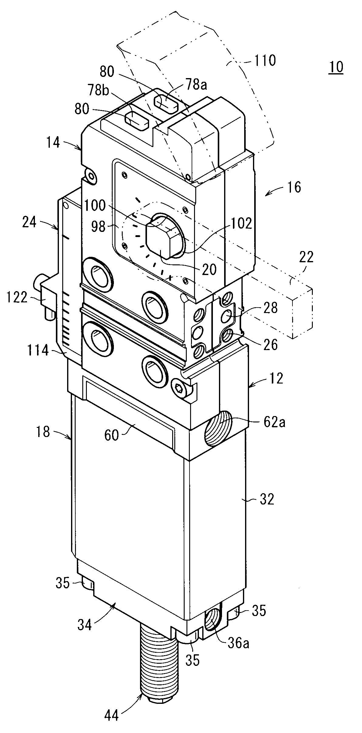
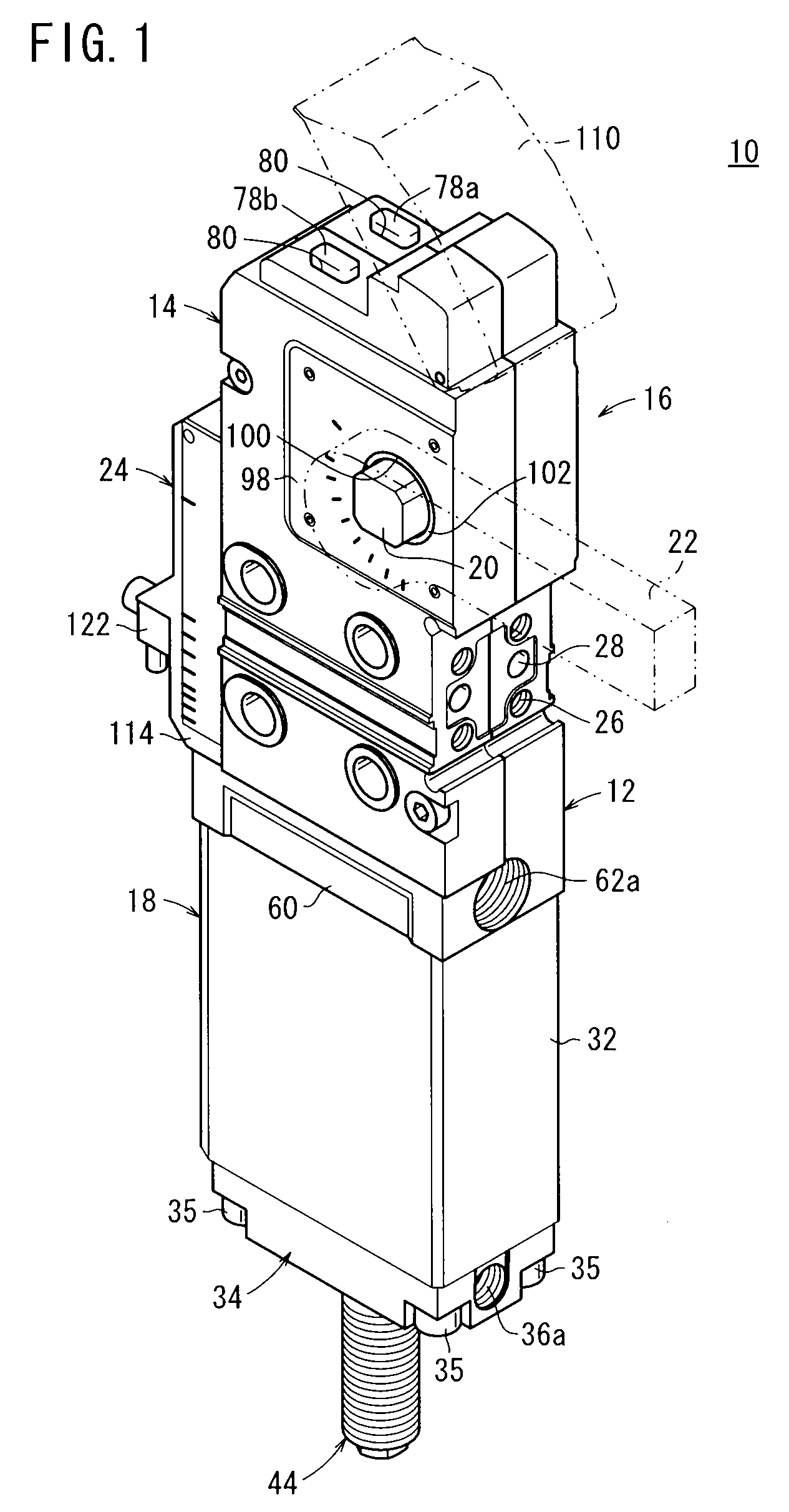
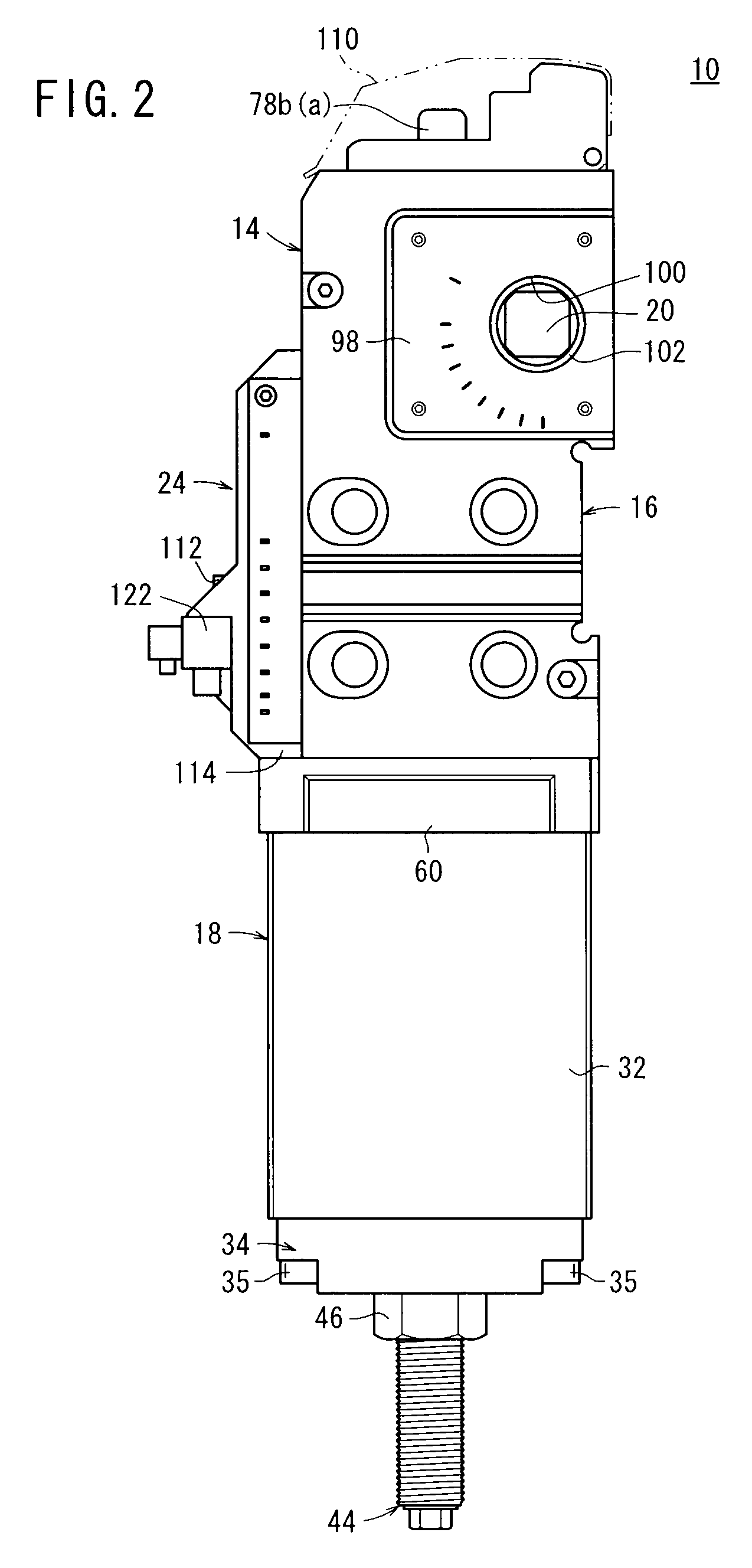
[0041]The clamp apparatus 10, as shown in FIGS. 1 to 3, includes a body (main body) 16 formed with a flattened shape from first and second casings 12, 14, a cylinder 18 connected to a lower end of the body 16, an arm (clamp arm) 22 connected to a rectangular bearing 20 projecting from the body 16 to the exterior thereof, and a detection mechanism 24 disposed on a side of the body 16 that detects a clamped state and an unclamped state of a workpiece (not shown) by the arm 22.

[0042]A plurality of fixing holes 26 into which unillustrated fixing screws are threaded for assembling the clamp apparatus 10 onto another member, and plural position determining holes 28 into which positioning pins (not shown) are inserted for setting the position of the clamp apparatus 10 when the clamp apparatus 10 is assembled, are formed on a side surface of the body 16.

[0043]The cylinder 18 is formed with a hollowed shape and includes a cylinder tube 32 having a cylinder chamber 30 (see FIG. 3) on the insi...


PUM


Abstract

A clamp device including a detection mechanism provided to detect whether the clamp device is in a clamped state or an unclamped state. The detection mechanism includes a tilt plate tiltably placed inside a switch holder installed on a body and a sliding rod displaced together with a piston rod and displaced in the direction normal to the tilt plate. When the sliding rod presses and tilts the tilt plate while a piston is displaced, a second detection switch detects that the clamp device is in the unclamped state.

Description

TECHNICAL FIELD[0001]The present invention relates to a clamp apparatus, which is capable of clamping a workpiece through a clamp arm rotated a predetermined angle under a displacement action of a piston.BACKGROUND ART[0002]Heretofore, for example, when a constituent element of an automobile or the like is welded, a clamp apparatus has been used in order to clamp the constituent element. Such a clamp apparatus includes a main body, a cylinder connected to the main body, and a clamp arm, which is rotated a predetermined angle, under a driving action of the cylinder, through a toggle link mechanism disposed inside of the main body. In addition, by displacing a piston and piston rod of the cylinder in an axial direction by means of a pressure fluid supplied to the cylinder, via the toggle link mechanism connected to the piston rod, the clamp arm is rotated through an operating angle based on the displacement amount of the piston. As a result, switching can occur between a clamped state...

Claims


Application Information

Patent Timeline
Patent Type & Authority Patents(United States)
IPC IPC(8): B23Q3/08B25B1/02B25B5/12B25B1/14B25B5/02
CPCB25B5/16B25B5/122B23Q3/082B23Q17/003B23Q2717/00
Inventor FUKUI, CHIAKITAKAHASHI, KAZUYOSHITAMAI, ATSUSHI
Owner SMC CORP
Why Eureka
Try Eureka