Air inlet valve for air compressor

An intake valve and air compressor technology, applied in mechanical equipment, machines/engines, liquid fuel engines, etc., can solve the problems of difficult installation and adjustment, many fault points, and many seals, and achieves anti-vibration and good dispersion. The effect of force, easy installation and adjustment

Active Publication Date: 2019-01-15
辰溪县宏兴新材料科技有限公司
View PDF6 Cites 0 Cited by
  • Summary
  • Abstract
  • Description
  • Claims
  • Application Information

AI Technical Summary

Problems solved by technology

[0002] The intake valve on the commonly used screw air compressor includes a valve body, which is provided with an air inlet and an air outlet, and a check valve element is arranged in the valve body. A circlip is installed inside the air port, and a sealing ring is installed inside the circlip to provide the valve plate in the check valve element in the valve body and form a sealing pair with it. This structure has many seals and many failure points. And with the expansion of the air inlet, the size of the spring is also larger, making it difficult to install and adjust

Method used


Image

  • Air inlet valve for air compressor
  • Air inlet valve for air compressor
  • Air inlet valve for air compressor

Examples


Embodiment 1

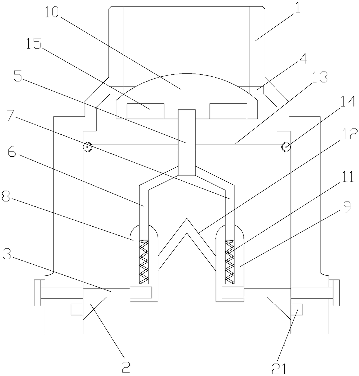
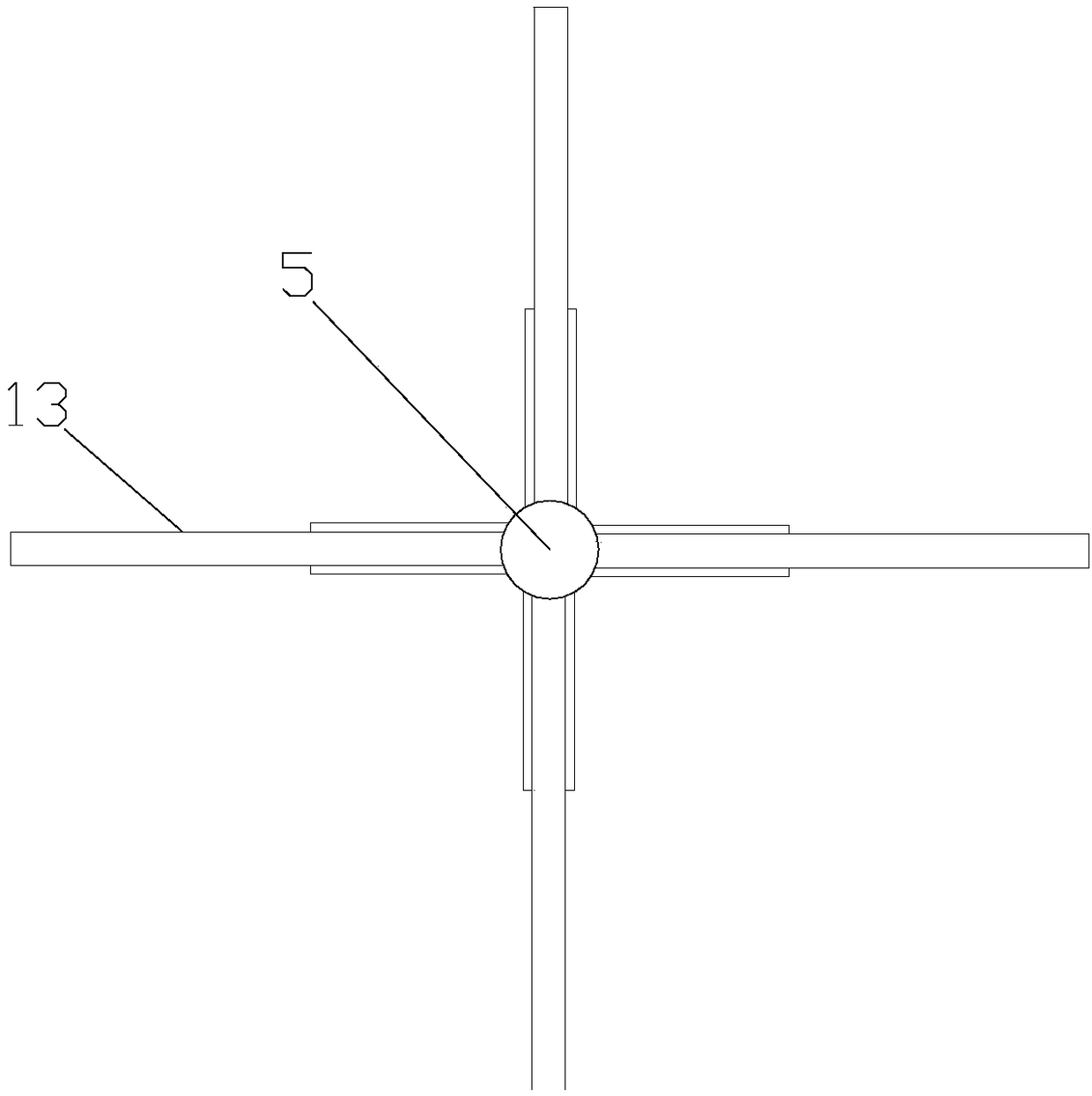
[0024] Such as Figure 1-3 As shown, an air intake valve for an air compressor includes an integrally formed valve casing 1, a valve core mechanism and a connecting body 3. A sealing rubber ring 4 is arranged inside the valve casing 1, and the top of the sealing rubber ring 4 Both the surface and the outer ring surface are bonded to the valve casing 1, and the valve core mechanism includes the valve stem 5, the first connecting rod 6, the second connecting rod 7, the first inserting sleeve 8, the second inserting sleeve 9 and rubber The ceramic valve core 10 matched with the sealing ring 4, the valve stem 5 is threadedly connected with the ceramic valve core 10, the first connecting rod 6 and the second connecting rod 7 are integrally arranged with the valve stem 5, and the first A connecting rod 6 and a second connecting rod 7 are all arranged in an obtuse angle, and a return spring 11 is arranged in the first inserting sleeve 8 and the second inserting sleeve 9, and the firs...

Embodiment 2

[0027] Such as Figure 1-3As shown, an air intake valve for an air compressor includes an integrally formed valve casing 1, a valve core mechanism and a connecting body 3. A sealing rubber ring 4 is arranged inside the valve casing 1, and the top of the sealing rubber ring 4 Both the surface and the outer ring surface are bonded to the valve casing 1, and the valve core mechanism includes the valve stem 5, the first connecting rod 6, the second connecting rod 7, the first inserting sleeve 8, the second inserting sleeve 9 and rubber The ceramic valve core 10 matched with the sealing ring 4, the valve stem 5 is threadedly connected with the ceramic valve core 10, the first connecting rod 6 and the second connecting rod 7 are integrally arranged with the valve stem 5, and the first A connecting rod 6 and a second connecting rod 7 are all arranged in an obtuse angle, and a return spring 11 is arranged in the first inserting sleeve 8 and the second inserting sleeve 9, and the first...


PUM


Abstract

The invention discloses an air inlet valve for an air compressor. The air inlet valve includes an integral valve shell, a valve core mechanism and a connecting body, the valve shell is internally provided with a sealing rubber ring, and the top face and the outer ring face of the sealing rubber ring are both bonded to the valve shell; the valve core mechanism comprises a valve rod, a first connection rod, a second connection rod, a first inserting barrel, a second inserting barrel and a ceramic valve core matched with the rubber seal ring, the valve rod is in threaded connection with the ceramic valve core, and the first connection rod and the second connection rod are both integrated with the valve rod; and the first connection rod and the second connection rod are both arranged in an obtuse angle shape, the first inserting barrel and the second inserting barrel are internally provided with reset springs correspondingly, the tail ends of the first connection rod and the second connection rod end are inserted into the first inserting barrel and the second inserting barrel correspondingly, and a connecting piece is arranged between the first inserting barrel and the second insertingbarrel. According to the air inlet valve for the air compressor, installation and adjustment are convenient.

Description

technical field [0001] The invention relates to an intake valve for an air compressor. Background technique [0002] The intake valve on the commonly used screw air compressor includes a valve body, which is provided with an air inlet and an air outlet, and a check valve element is arranged in the valve body. A circlip is installed inside the air port, and a sealing ring is installed inside the circlip to provide the valve plate in the check valve element in the valve body and form a sealing pair with it. This structure has many seals and many failure points. And as the air inlet expands, the size of the spring is also larger, making installation and adjustment difficult. Contents of the invention [0003] The technical problem to be solved by the present invention is to provide an air intake valve for an air compressor that is easy to install and adjust. [0004] In order to solve the above problems, the present invention adopts the following technical solutions: [00...

Claims


Application Information

Patent Timeline
Patent Type & Authority Applications(China)
IPC IPC(8): F04C18/16F04C29/12F04C29/00
CPCF04C18/16F04C29/00F04C29/124
Inventor 不公告发明人
Owner 辰溪县宏兴新材料科技有限公司
Why Eureka
Try Eureka