Adjustable airflow duct

a technology of airflow duct and adjustable duct, which is applied in the direction of electrical equipment, electrical apparatus, electrical apparatus contruction details, etc., can solve the problems of undesired warmness of adjacent air, and achieve the effect of convenient adjustment of duct length

Pending Publication Date: 2022-06-09
MASTERCARD INT INC
View PDF5 Cites 0 Cited by
  • Summary
  • Abstract
  • Description
  • Claims
  • Application Information

AI Technical Summary

Benefits of technology

[0005]Among other things, provision of a duct including relatively shiftable first and second duct sections that extend in the longitudinal direction to cooperatively present an adjustable longitudinal duct length, and a drive mechanism operably coupled to said first and second sections to control relative shifting of the sections in the longitudinal direction to thereby adjust the longitudinal duct length to correspond with the longitudinal dimension, facilitates efficient adjustment of the duct length to effectively direct cool air to an electronic device having an intake side positioned at any of numerous intermediate longitudinal positions.

Problems solved by technology

In some instances, the adjacent air may be undesirably warm due to, among other factors, the position of the air intake portion within the rack or, more broadly, within the data center.

Method used


Image

  • Adjustable airflow duct
  • Adjustable airflow duct
  • Adjustable airflow duct

Examples


Embodiment Construction

[0021]The present invention is susceptible of embodiment in many different forms. While the drawings illustrate, and the specification describes, certain preferred embodiments of the invention, it is to be understood that such disclosure is by way of example only. There is no intent to limit the principles of the present invention to the particular disclosed embodiments.

[0022]Furthermore, unless specified or made clear, the directional references made herein with regard to the present invention and / or associated components (e.g., top, bottom, upper, lower, inner, outer, etc.) are used solely for the sake of convenience and should be understood only in relation to each other. For instance, a component might in practice be oriented such that faces referred to as “top” and “bottom” are sideways, angled, inverted, etc. relative to the chosen frame of reference.

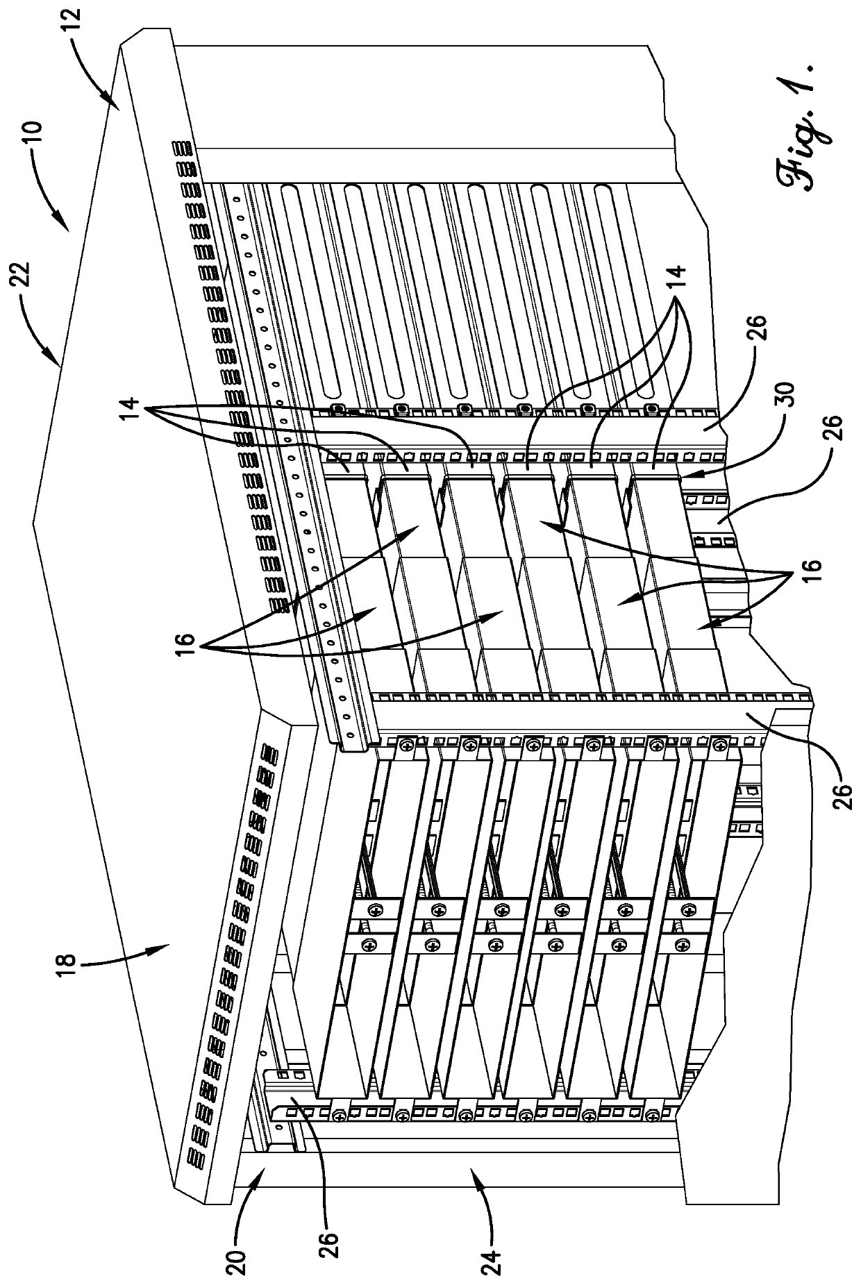
Data Center Rack Assembly

[0023]Turning now to FIG. 1, a data center rack assembly 10 is illustrated. The data center rack assemb...


PUM


Abstract

A data center rack assembly includes a rack, an electronic device, and an adjustable air duct. The rack includes a frame defining opposite first and second rack sides spaced apart in a longitudinal direction. The electronic device presents an intake side configured to receive air therethrough for passage into the electronic device. The electronic device is mounted to the frame such that the intake side is disposed intermediately between the rack sides and is spaced from the first rack side to define a longitudinal dimension therebetween. The duct includes relatively shiftable first and second duct sections that extend in the longitudinal direction to cooperatively present an adjustable longitudinal duct length, and a drive mechanism operably coupled to the first and second sections to control relative shifting of the sections in the longitudinal direction to thereby adjust the longitudinal duct length to correspond with the longitudinal dimension.

Description

CROSS REFERENCE TO RELATED APPLICATION[0001]The present application claims priority from U.S. Provisional Application No. 63 / 123,090 filed Dec. 9, 2020, entitled ADJUSTABLE AIRFLOW DUCT, which is hereby incorporated in its entirety by reference herein.BACKGROUND OF THE INVENTION1. Field of the Invention[0002]The present invention relates generally to an adjustable airflow duct for use in a data center cabinet or rack.2. Discussion of the Prior Art[0003]Those of ordinary skill in the art will appreciate that data centers often include multiple cabinets or racks in which various hardware devices are supported. For instance, one or more servers, routers, security appliances, controllers, hard drives, switches, and so on might be supported in a given cabinet or rack. Such devices may include an air intake portion that draws in adjacent air. In some instances, the adjacent air may be undesirably warm due to, among other factors, the position of the air intake portion within the rack or, ...

Claims


Application Information

Patent Timeline
Patent Type & Authority Applications(United States)
IPC IPC(8): H05K7/20
CPCH05K7/20145H05K7/20736
Inventor LATORRE, MICHAELMCCLINTOCK, TRAVIS
Owner MASTERCARD INT INC
Why Eureka
Try Eureka