Forend grip assembly for receipt upon an unaltered host weapon

a technology for receiving and host weapons, applied in the field of firearms, can solve the problems of unnatural method of holding forward control surfaces of rifles, less than optimal arm orientation or configuration, and unsatisfactory gripping size for operators

Active Publication Date: 2012-08-21
RM EQUIP
View PDF55 Cites 83 Cited by
  • Summary
  • Abstract
  • Description
  • Claims
  • Application Information

AI Technical Summary

Benefits of technology

[0014]The subject grip assembly is configurable to attach to forearms of a variety of weapons, more particularly, those commonly known as the M16 rifle, the M4 rifle, and the AR-15 rifle. The grip assembly of the subject invention will also attach to these style forearms when these forearms are attached to other makes and models of host weapons. Furthermore, and as should be readily appreciated in connection to the subsequent detailed description, modifications in the nature / configuration of mating services of mounting plate permit the otherwise novel features of the grip assembly to provide enhanced forend gripping to other known styles of host weapon, more particularly forearms thereof. More specific features and advantages obtained in view of those features will become apparent with reference to the drawing figures and DETAILED DESCRIPTION OF THE INVENTION.

Problems solved by technology

The diameter of the forearm is generally sized to the functional requirements of the rifle, and not the optimum gripping size for an operator.
The aforementioned described method of holding the forward control surface of the rifle is unnatural, uncomfortable, and fatiguing.
This position constantly stress the muscles in the operator's lower and upper arm, and is a less-than optimal orientation or configuration for the arm to support the weight of the rifle for an extended period of time.
Likewise, hunters often engage in their activities for lengthy periods, and, sporting shooters handle their rifles for hours at a time practicing their competition skills.
Although accessory-mounting rails for installation under a weapon barrel are known, in addition to being a hindrance to a universal forend grip, the host weapon requires alteration with this approach.
Thus, the lack of forward gripping surface persists for operators of all rifles with rounded forearms.
Adding an accessory-mounting rail to a weapon to provide an attachment surface for a vertical grip adds complexity to the weapon that is not required, and hardly advantageous.

Method used


Image

  • Forend grip assembly for receipt upon an unaltered host weapon
  • Forend grip assembly for receipt upon an unaltered host weapon
  • Forend grip assembly for receipt upon an unaltered host weapon

Examples


Embodiment Construction

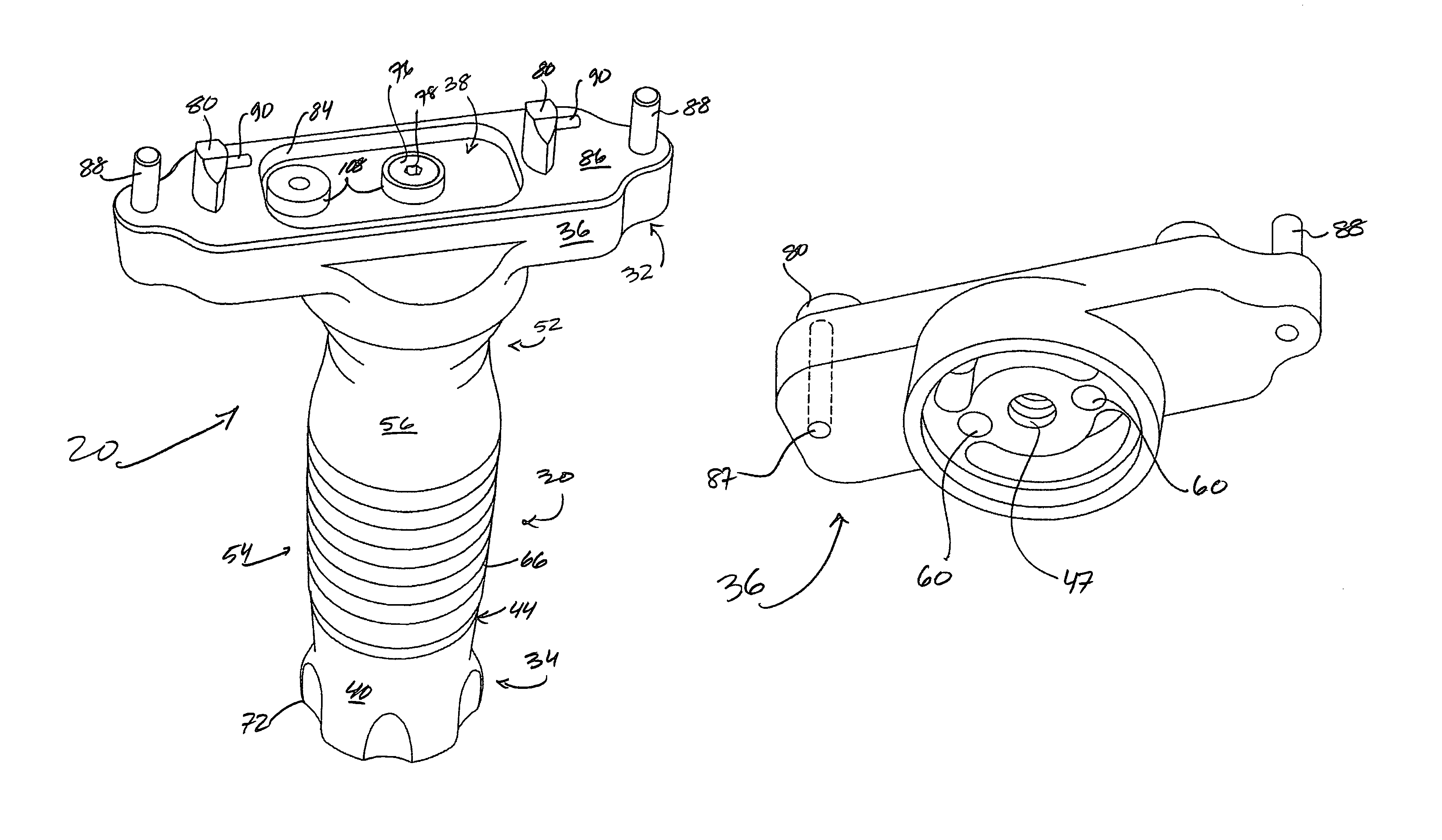
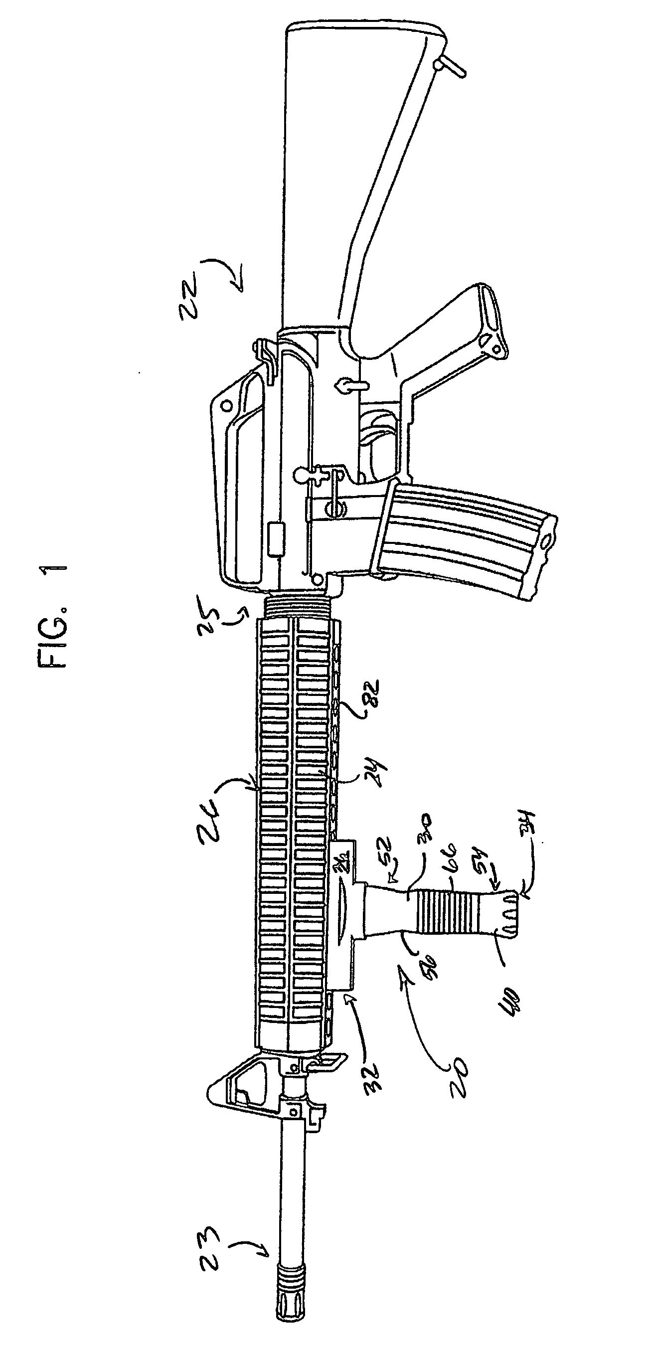
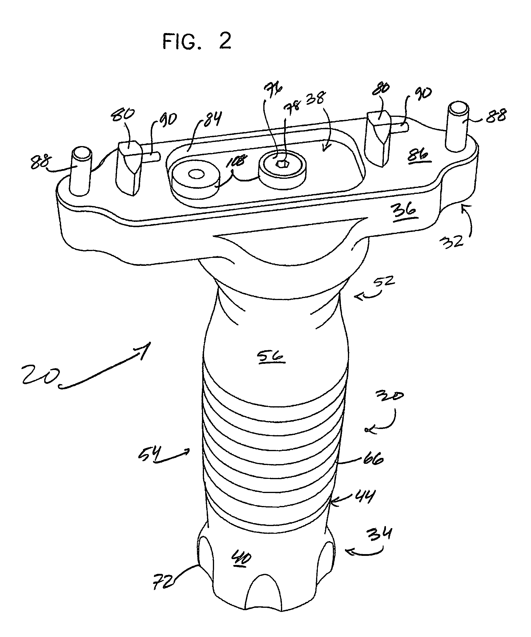
[0032]A grip assembly 20 of the subject invention is shown in FIG. 1, more particularly, the assembly 20 is illustrated operatively united to a weapon 22, i.e., a host weapon, more particularly still, to a lower portion 24 of an unaltered forend 26, namely the CAR forend of a Bushmaster M4 carbine. The FIG. 1 assembly per se is the subject of FIGS. 2-5; the assembly and forend relationships the subject of FIGS. 6-10; and, an advantageous adaptation thereof the subject of FIGS. 11-13. Functionally advantageous, non-limiting alternate assemblies are depicted in FIGS. 14-16 on the one hand, and FIG. 17 on the other hand, more particularly, alternate weapon interface structures for an M16 forearm and HK-G36 forearm, respectively.

[0033]In as much as the Bushmaster, M16, and HK-G36 assembly embodiments have or include characteristic elements or subassemblies, e.g., a weapon interface and / or a mount body or platform (see / compare FIGS. 2, 14, and 17), a variety of common assembly elements e...


PUM


Abstract

A weapon grip assembly for mating with a weapon without tools is provided. The assembly generally includes a handle, a weapon interface supported by the handle, and an actuator operatively engageable in furtherance of securely affixing the weapon interface to a lower portion of an unaltered handguard of the weapon. The weapon interface generally includes a mount body, and an actuatable locking structure reversibly extendible from the mount body via operative engagement of the actuator.

Description

[0001]This is an international patent application filed under 35 U.S.C. §363 claiming priority under 35 U.S.C. §119(e) (1), of provisional application Ser. No. 60 / 742,228, having a filing date of Dec. 5, 2005 and incorporated herein by reference in its entirety.TECHNICAL FIELD[0002]The present invention generally relates to firearms, more particularly, to a forend grip for receipt upon a host weapon, more particularly, a grip reversibly receivable within one or more spaced apart apertures of an unaltered forend of a host weapon.BACKGROUND OF THE INVENTION[0003]Weapons are fired with a purpose: to hit an intended target. A basic tenant of shooting is that the operator must have complete control of the weapon in order to make it perform accurately. A firm grip of the weapon is basic to achieving control thereof, and thus, accurate performance.[0004]Because the functional characteristics of weapons, more particularly, rifles, cause them to be elongated, a forward gripping surface of a ...

Claims


Application Information

Patent Timeline
Patent Type & Authority Patents(United States)
IPC IPC(8): F41C23/16
CPCF41C23/16
Inventor GRIFFIN, TODD
Owner RM EQUIP
Why Eureka
Try Eureka