Signal line correction method and apparatus

a signal line and correction method technology, applied in the field of signal line correction methods and apparatuses, can solve the problems of preventing the generation of such artifacts, changing the intensity of a signal read out by a signal line adjacent to the faulty signal line, and changing the intensity of a signal read out by the adjacent signal line in the readout circui

Inactive Publication Date: 2012-08-21
FUJIFILM CORP
View PDF5 Cites 3 Cited by
  • Summary
  • Abstract
  • Description
  • Claims
  • Application Information

AI Technical Summary

Benefits of technology

This approach allows for accurate signal correction without losing high frequency information, preventing artifacts and ensuring that the corrected radiation image signals represent the original image data more accurately.

Problems solved by technology

Such a fault poses a problem that the intensity of a signal read out by a signal line adjacent to the faulty signal line is changed due to a response delay.
Further, a charge leaks from the faulty signal line to an adjacent signal line, causing a problem that the intensity of a signal read out by the adjacent signal line is changed.
There has also been a problem, however, that the intensity of a signal read out by a first target signal line in the readout circuit is changed due to a response delay.
Performance of the interpolation using the signal read out by the normal signal line adjacent to the faulty signal line, however, causes information of the signal read out by the abnormal signal line to be lost completely.
Further, for the signal read out by the first target signal line of the readout circuit, performance of interpolation using a signal of an adjacent signal line causes the same problem as described above.

Method used


Image

  • Signal line correction method and apparatus
  • Signal line correction method and apparatus
  • Signal line correction method and apparatus

Examples


first embodiment

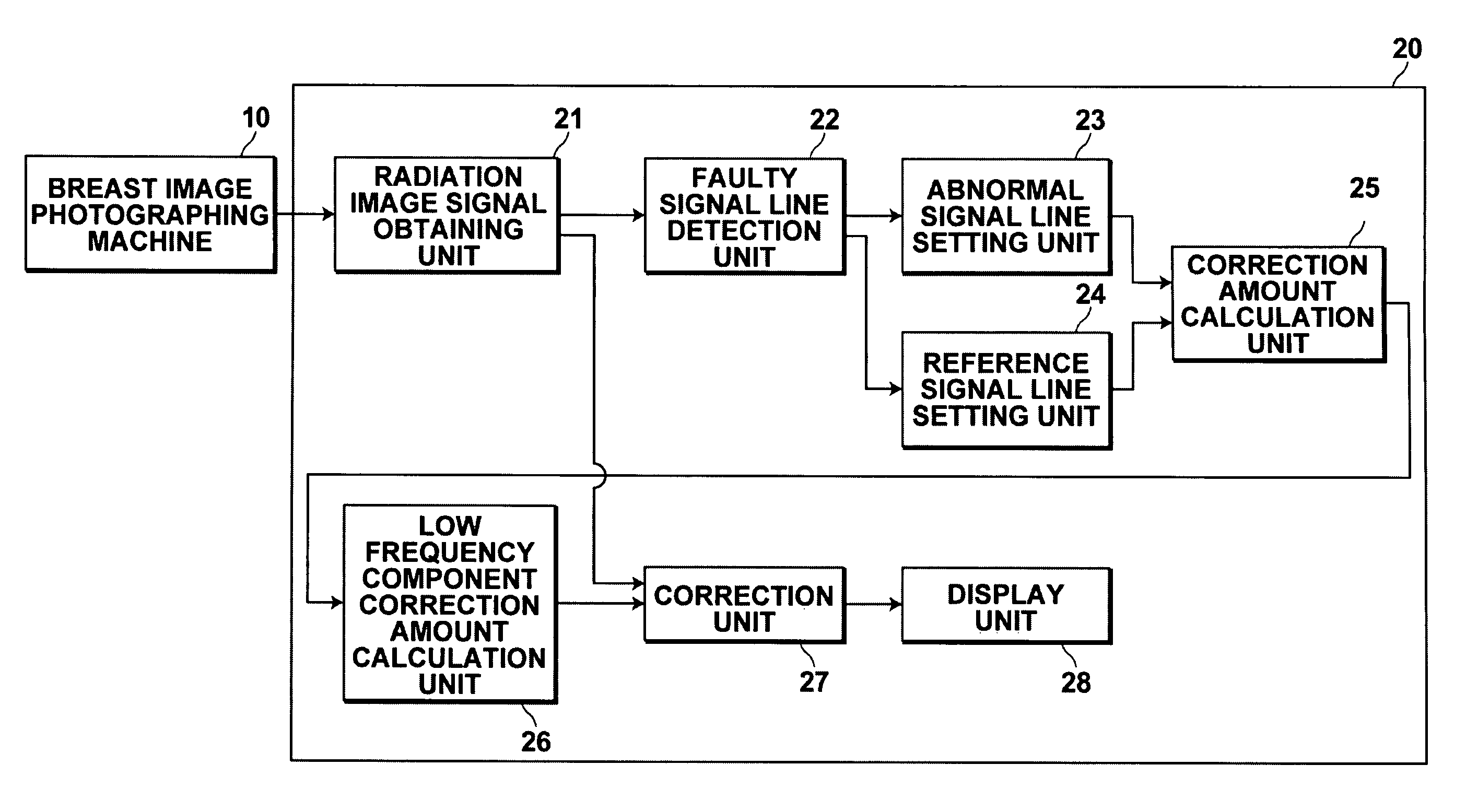
[0059]Hereinafter, a breast image photographing / display system incorporating the signal line correction apparatus of the present invention will be described with reference to the accompanying drawings. The breast image photographing / display system has characteristic features in the fault correction method of linear electrodes in a radiation image detector of the system, but the schematic configuration of the entire system will be described first. FIG. 1 illustrates a schematic configuration of the breast image photographing / display system.

[0060]The breast image photographing / display system according to the present embodiment includes breast image photographing machine 10 for photographing a breast radiation image and breast image display unit 20 for displaying a breast radiation image based on radiation image data representing the breast radiation image taken by breast image photographing machine 10.

[0061]Breast image photographing machine 10 includes radiation emission unit 2 havin...

second embodiment

[0094]Abnormal signal line setting unit 23a of breast image display unit 20a of the second embodiment sets signal line 38a which is the first readout target of each readout circuit 60 shown in FIG. 5 as an abnormal signal line. Here, signal line 38a which is the first readout target of each readout circuit 60 refers to the signal line connected to charge amplifier 50 which will be connected to A / D converter 60b first by multiplexer 60a.

[0095]Reference signal line setting unit 24a of breast image display unit 20a of the second embodiment sets a signal line adjacent to the abnormal signal line set by abnormal signal line setting unit 23a and having a normal amount of signal as a reference signal line.

[0096]An operation of the breast image photographing / display system of the present embodiment will now be described with reference to FIG. 10 and the flowchart shown in FIG. 11.

[0097]After photographing of a radiation image is performed, a radiation image signal representing a breast rad...


PUM


Abstract

A method for use with a radiation image detector, including the steps of detecting a faulty signal line having a signal amount less than a predetermined threshold value based on radiation image signals read out from the detector, setting a signal line adjacent to the faulty signal line as an abnormal signal line and a signal line adjacent to the abnormal signal line and having a normal amount of signal as a reference signal line, calculating the difference between a signal read out by the abnormal signal line and a signal read out by the reference signal line as a correction amount, calculating a low frequency component correction amount by removing a high frequency component from the calculated correction amount, and performing a correction on the signal read out by the abnormal signal line by adding the calculated low frequency component correction amount to the signal.

Description

CROSS-REFERENCE TO RELATED APPLICATIONS[0001]The present application claims priority from Japanese Patent Application No. 2008-186907, filed Jul. 18, 2008, the contents of which are herein incorporated by reference in their entirety.BACKGROUND OF THE INVENTION[0002]1. Field of the Invention[0003]The present invention relates to a signal line correction method and apparatus for performing a signal line correction on a radiation image signal read out from a radiation image detector.[0004]2. Description of the Related Art[0005]Various types of radiation image detectors that receive radiation transmitted through a subject to record a radiation image of the subject are proposed and put into practical use in the medical and other industrial fields.[0006]The radiation image detectors include, for example, radiation image detectors using amorphous selenium that generate charges by receiving radiation and as such radiation image detectors, a so-called optical readout type and a TFT readout t...

Claims


Application Information

Patent Timeline
Patent Type & AuthorityPatents(United States)
IPC IPC(8): G06K9/00
CPCH04N5/32H04N5/3658H04N25/677
InventorKUWABARA, TAKAOYAMADA, HIDEYUKI
OwnerFUJIFILM CORP