Transmission and method of shift control for transmission

a shift control and transmission technology, applied in the direction of instruments, mechanical equipment, gearing, etc., can solve the problems of slowness or retardation, driver's feelings of annoyance or unpleasantness, annoyance or unpleasantness,

Inactive Publication Date: 2012-09-04
AISIN AI CO LTD +1
View PDF4 Cites 8 Cited by
  • Summary
  • Abstract
  • Description
  • Claims
  • Application Information

AI Technical Summary

Benefits of technology

[0027]In a fifth optional setting of the present transmission, the rapid-deceleration judge can preferably comprise a deceleration calculator for calculating deceleration, and an accessible map for making it possible to judge whether the vehicle is in the rapid-deceleration condition or in ordinary-deceleration condition on the basis of comparison between a calculated deceleration and a state of the vehicle, and can preferably apply a current deceleration and a current state of the vehicle to the accessible map to judge whether the vehicle is in the rapid-deceleration condition or in the ordinary-deceleration condition.
[0058]In the fifth optional setting that is relevant to the present shift-control method for transmission, the controller is operated to calculate deceleration, and to access a map for enabling the controller to judge of which conditions a vehicle is in. Then, the controller is operated to apply the resultant calculated deceleration and a vehicular condition to the accessible map, or to consult the accessible map using these data, in order to judge whether the vehicle is decelerating rapidly or not. As a result, the present shift-control method enables the controller to judge or determine that a vehicle is in rapid-deceleration condition more accurately.

Problems solved by technology

However, when a driver carries out change-speed operations by a conventional transmission that uses a shift map, he or she might feel slowness or retard to suffer from feelings of annoyance or unpleasantness because ordinary traveling conditions are simulated to prepare the shift map.
As a result, the driver might feel annoyance or unpleasantness because of the time that has elapsed since he or she has issued a change-speed request.
Alternatively, he or she might feel annoyance or unpleasantness because the conventional transmission has shifted to an inappropriate change-speed stage.
Moreover, even during deceleration, the conventional transmission might give the driver feelings of annoyance or unpleasantness because it might select the change-speed stage one after another accompanied by rapid changes in the vehicle speed to result in the occurrence of torque fluctuation.

Method used


Image

  • Transmission and method of shift control for transmission
  • Transmission and method of shift control for transmission
  • Transmission and method of shift control for transmission

Examples


embodiment no.1

Embodiment No. 1

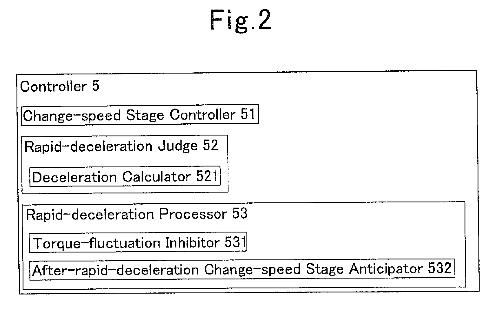
[0089]As illustrated in FIG. 2, the present transmission 1 according to Embodiment No. 1 uses the controller 5 that comprises the change-speed controller 51, a rapid-deceleration judge 52, and a rapid-deceleration processor 53. FIG. 2 is an explanatory diagram which depicts the controller 5 alone that is taken out of the present transmission 1.

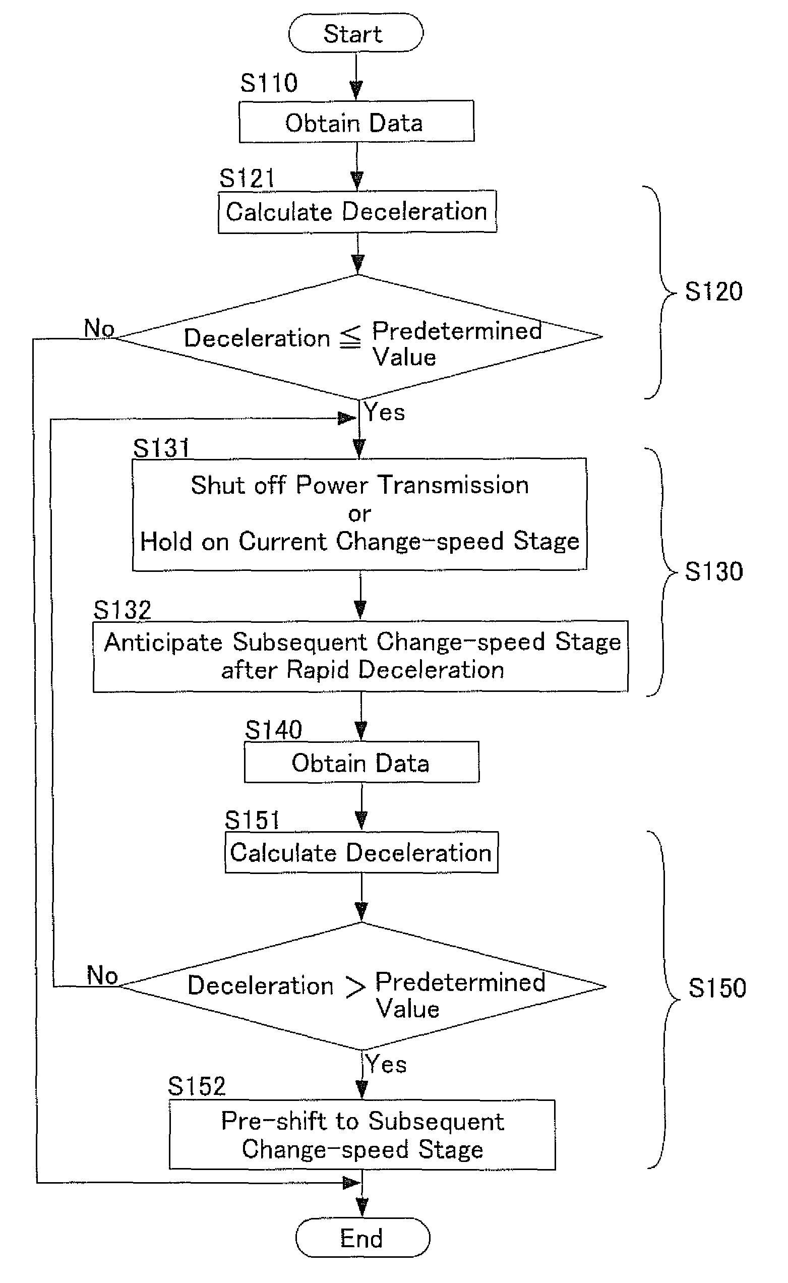
[0090]The rapid-deceleration judge 52 is provided with a deceleration calculator 521. The deceleration calculator 521 calculates deceleration. The deceleration is a rate of decrease of a vehicle's speed within a constant period of time, and is expressed by negative values. Note herein that the greater the absolute value of the deceleration is the greater extent a vehicle decreases the speed. The deceleration calculator 521 uses an acceleration sensor or speed sensor to find the deceleration from vehicle speeds, accelerator opening magnitudes, input revolutions, temperatures (e.g., oil temperatures, engine-coolant temperatures, ...

embodiment no.2

Embodiment No. 2

[0098]As illustrated inFIG. 4, the present transmission 1 and shift-control method for transmission according to Embodiment No. 2 uses a controller 5B that comprises a change-speed controller 51, a rapid-deceleration judge 54 and a rapid-deceleration processor 53. As shown in the drawing, the controller 5B being directed to the transmission 1 according to Embodiment No. 2 is a device that is similar to the controller 5 being directed to the transmission according to Embodiment No. 1. Note however that the rapid-deceleration judge 54 substitutes for the rapid-deceleration judge 52, one of the elements of the controller 5. In essence, the transmission 1 and shift-control method for transmission according to Embodiment No. 2 produce the same advantageous effects as those of the transmission 1 and shift-control method for transmission according to Embodiment No. 1.

[0099]Meanwhile, the controller 5B comprises the same rapid-deceleration processor 53 as that the controller...

embodiment no.3

Embodiment No. 3

[0104]As illustrated in FIG. 6, the present transmission 1 and shift-control method for transmission according to Embodiment No. 3 uses a controller 5C that comprises a change-speed controller 51, a rapid-deceleration judge 52 and a rapid-deceleration processor 55. As shown in the drawing, the controller 5C being directed to the transmission 1 according to Embodiment No. 3 substitutes for the controller 5 being directed to the transmission 1 according to Embodiment No. 1. Note that the rapid-deceleration processor 55 substitutes for the rapid-deceleration processor 53, one of the elements of the controller 5. In essence, the transmission 1 and shift-control method for transmission according to Embodiment No. 3 produce the same advantageous effects as those of the transmission 1 and shift-control method for transmission according to Embodiment No. 1.

[0105]Meanwhile, the controller 5B comprises the same rapid-deceleration judge 52 as that the controller 5 being relevan...


PUM


Abstract

A transmission includes a controller that has a rapid-deceleration judge and a rapid-deceleration processor. The rapid-deceleration judge judges whether a vehicle is decelerating rapidly or not. The rapid-deceleration processor includes a torque-fluctuation inhibitor, and an after-rapid-deceleration change-speed stage anticipator. The torque-fluctuation inhibitor shuts off power transmission from a power source, or holds power transmission by way of a current change-speed stage or lower, when the vehicle is decelerating rapidly. The after-rapid-deceleration change-speed stage anticipator anticipates a subsequent change-speed stage being adapted for restarting or reaccelerating the vehicle that has come out of rapid deceleration.

Description

INCORPORATION BY REFERENCE[0001]The present invention is based on Japanese Patent Application No. 2009-72,023, filed on Mar. 24, 2009, the entire contents of which are incorporated herein by reference.BACKGROUND OF THE INVENTION[0002]1. Field of the Invention[0003]The present invention relates to a transmission, and a method of shift control for transmission. In particular, it relates to a dual-clutch transmission comprising two clutches, and a method of shift control for such dual-clutch transmission.[0004]2. Description of the Related Art[0005]One of transmissions for automobile is a dual-clutch transmission that comprises two clutches, namely, which uses a so-called dual-clutch mechanism, (hereinafter abbreviated to as “DCT”). Upon switching change-speed stages, the DCT is characterized in that it can carry out shifting operations quickly without cutting off or interrupting torque transmissions.[0006]As disclosed in Japanese Unexamined Patent Publication (KOKAI) Gazette No. 2007-...

Claims


Application Information

Patent Timeline
Patent Type & Authority Patents(United States)
IPC IPC(8): F16H3/08F16H59/00F16H61/04
CPCF16H61/688F16H2059/186F16H2306/18Y10T74/19251Y10T74/19228Y10T74/19074F16H2312/18
Inventor HATORI, HIROKIMIYAZAKI, TAKESHIGEITO, YOSHIKITOYODA, HIROSHINAGAMI, KIYOSHITAKEUCHI, ATSUSHI
Owner AISIN AI CO LTD
Why Eureka
Try Eureka