Chassis with wheels

a technology of chassis and wheels, applied in the direction of manipulators, vehicle components, superstructure subunits, etc., can solve the problems of poor robot performance in surmounting obstacles, robots are unable to work normally, and service robots barely have the performance to overcome obstacles

Active Publication Date: 2020-01-16
UBTECH ROBOTICS CORP LTD
View PDF2 Cites 4 Cited by
  • Summary
  • Abstract
  • Description
  • Claims
  • Application Information

AI Technical Summary

Benefits of technology

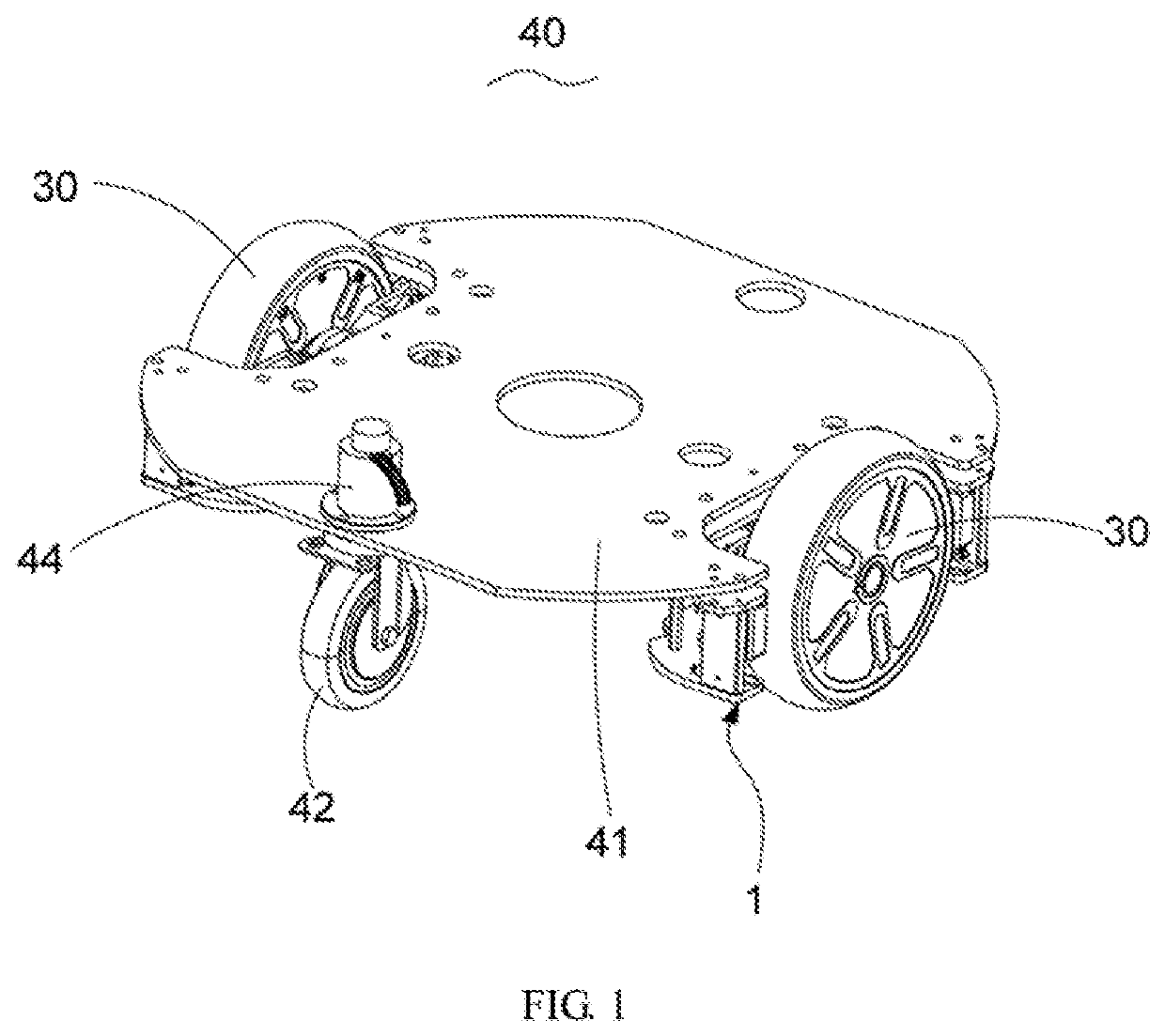
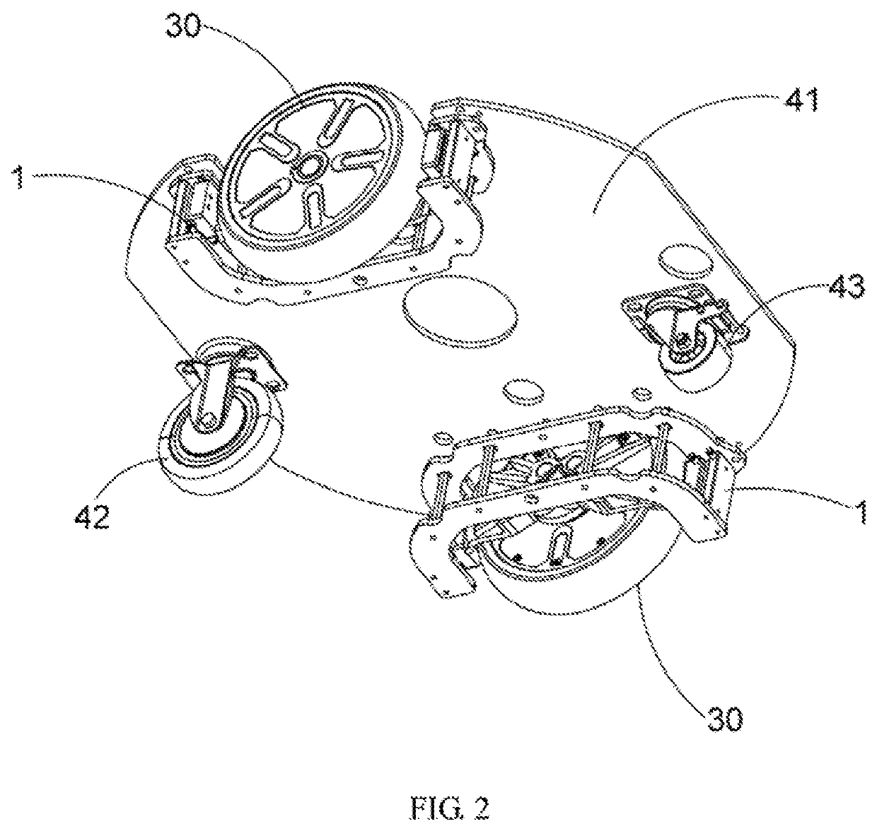
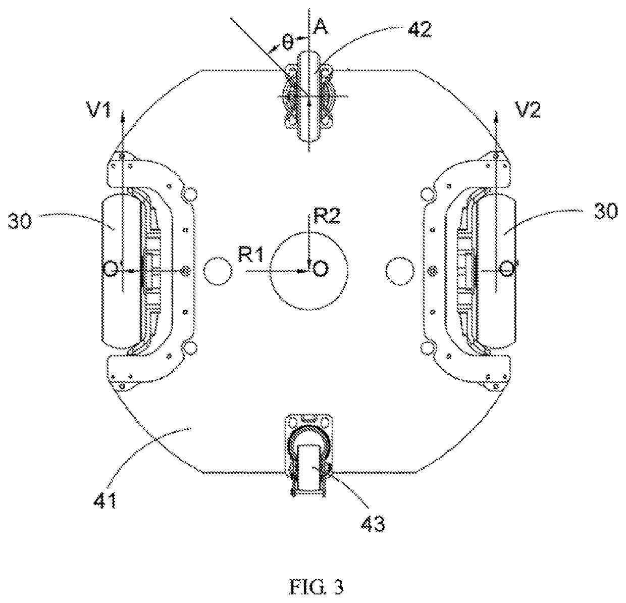
[0030]In a further embodiment of the present application, a robot is provided, including the chassis as stated above, as shown in FIG. 8. When the chassis according to the application is utilized in the robot, the mounting racks 10 are moved downward together with the frame 41 with respect to the hanging racks 20 due to the weight of the robot loaded on the frame 41, and meanwhile the spring elements 12 are tensioned. In the case that the robot walks in a flat road surface, the chassis works as a general four-wheeled chassis due to the adjustment and the slant arrangement of the spring elements 12. In the case that the robot walks in a rough road surface, the hanging racks 20 and the driving wheels 30 are moved upward in an uphill or moved downward in a groove, such that the driving wheels 30 are held being attached to the road surface without being suspended or slipped with respect to the road surface. Additionally, the suspension system 1 ensures a more smooth movement of the robot such that a rapid deceleration to some extent is acceptable to the robot, and meets a requirement of movement for a robot with a center of gravity in a high level such that no tilting accident of the robot occurs. As an alternative, the above-mentioned hanging unit 1 can be provided to the robot by means of other structures, as long as the above-mentioned effects can be achieved. Meanwhile, the front guiding wheel 42 has the capability of active adjustment that the rotational angle of the front guiding wheel 42 can be adjusted according to the speeds of the driving wheels 30, so that the front guiding wheel 42 can have its diameter to be designed larger to make the robot perform better and more stably in surmounting obstacles. The robot is provided with a main control board therein for controlling the operation of the robot. The first driving motor 44 of the front guiding wheel 42 and the two second driving motors are electrically coupled to the main control board which in turn controls the first driving motor 44 to adjust the rotational angle of the front guiding wheel 42 on the basis of the condition of the road surface and the real-time walking state of the robot.

Problems solved by technology

These service robots barely have performances for surmounting obstacles as they mostly work indoor on flat floors.
In practical applications, rough terrains are inevitable even in indoor places such as hotels, airports or the like, and thus the robots are unable to work normally as soon as encountering the rough terrains.
And further due to the limitation of the universal wheel itself, the universal wheel has a relatively small diameter and thus has a limited capability of surmounting obstacles, resulting in poor performance of the robot in surmounting obstacles.

Method used


Image

  • Chassis with wheels
  • Chassis with wheels
  • Chassis with wheels

Examples


Embodiment Construction

[0012]Embodiments of the present application are described in detail below with reference to the appending drawings. Equal and / or similar elements in the drawings can here be designated by equal and / or similar reference signs. The embodiments described below with reference to the drawings are intended to be illustrative of the application and are not to be construed as limiting the application.

[0013]In the description of the present application, it should be understood that the terms “length”, “width”, “upper”, “lower”, “front”, “rear”, “left”, “right”, “vertical”, “horizontal”, “top”, “bottom”, “inside”, “outside” and the like are based on the orientation or positional relationship shown in the drawings, and are merely for convenience of description of the present application and for a simplified description, rather than indicating or implying that the device or component referred to must have a particular orientation, or must be constructed or operated in a particular orientation,...


PUM


Abstract

The present disclosure provides a chassis comprising a frame, two hanging units symmetrically provided at both sides of the frame, and a front guiding wheel and a rear universal wheel provided below the frame, wherein each of the hanging units comprises a mounting rack fixedly connected to the frame, a hanging rack slidably connected to the mounting rack, and a driving wheel rotatably connected to the hanging rack, and the front guiding wheel is provided with a first driving motor, and the driving wheel of each hanging unit is driven by a second driving motor, and wherein a closed loop speed control system is formed between the first driving motor and both second driving motors, such that a rotational angle of the front guiding wheel is adjustable via the first driving motor when revolving speeds of both second driving motors are changed.

Description

CROSS REFERENCE TO RELATED APPLICATIONS[0001]This application claims priority to Chinese Patent Application No. 201810772271.7, filed Jul. 13, 2018, which is hereby incorporated by reference herein as if set forth in its entirety.BACKGROUND1. Technical Field[0002]The present application relates to a field of chassis technology, and in particular to a chassis with wheels.2. Description of Related Art[0003]Recently, robot technology has been developed rapidly, and mobile service robots have been gradually used in commercial applications. Most of these service robots are wheeled robots and used for receiving and guiding customers. These service robots barely have performances for surmounting obstacles as they mostly work indoor on flat floors. In practical applications, rough terrains are inevitable even in indoor places such as hotels, airports or the like, and thus the robots are unable to work normally as soon as encountering the rough terrains. The reason is that in a current chass...

Claims


Application Information

Patent Timeline
Patent Type & Authority Applications(United States)
IPC IPC(8): B62D21/10B62D25/20
CPCB25J5/007B62D25/20B62D21/10B62D21/18B62D61/04B62D63/02Y02T10/72
Inventor XIONG, YOUJUNZHAO, KUNLEIYU, WENHUAZHOU, LIBINGZHAO, QI
Owner UBTECH ROBOTICS CORP LTD
Why Eureka
Try Eureka