
Erectable arm assembly for use in boreholes

a technology of erectable arms and boreholes, which is applied in the direction of surveying, artificial islands, core removal, etc., can solve the problems of incorrectly determining various parameters, no one drilling method is satisfactory for all radii of curvature, etc., and achieve the effect of preventing jamming of the arm member

Inactive Publication Date: 2002-04-18
TRUEMAN ROBERT +2
View PDF1 Cites 84 Cited by
  • Summary
  • Abstract
  • Description
  • Claims
  • Application Information

AI Technical Summary

Benefits of technology

[0012] It is an object of the invention to provide a method and assembly which may overcome the abovementioned disadvantages or provide the consumer with a useful or commercial choice.
[0023] The tight radius bend helps eliminate a lot of the problems encountered with dewatering larger radius deviated wells by requiring only a basic foot pump inserted into the existing borehole to drain all of the lateral boreholes branching from that well.
[0032] It is preferred that the arm member is configured to allow it to support a flexible hose drill string. Thus, when the assembly is placed in position, and the arm member is moved to its extended position, the arm member can be maintained in its extended position and a flexible hose drill string can be passed down the existing borehole through an upper portion of the tubular body and along the arm member thereby positioning the drill string for lateral borehole formation.
[0039] To facilitate smooth movement of the arm member, at least one flushing jet may be provided to flush away any cuttings which may settle on the assembly and especially around the arm member as the cutting device is operative.
[0042] In another variation to the invention, the arm member can have cutting means to cut a slot into the wall of the borehole as the arm member moves towards its extended position. In this embodiment, the assembly can cut a slot as the arm member extends from the main body and therefore the need for a cavity may be eliminated or an undersized cavity may be used.
[0048] Correctly determining that the cutting device is fully within the arm member is important to prevent jamming of the arm member upon its retraction.

Problems solved by technology

No one drilling method is satisfactory for all radii of curvature.
A disadvantage with existing whipstocks and other similar assemblies is in correctly determining various parameters in the down hole and drilling process.

Method used


Image

  • Erectable arm assembly for use in boreholes
  • Erectable arm assembly for use in boreholes
  • Erectable arm assembly for use in boreholes

Examples


Embodiment Construction

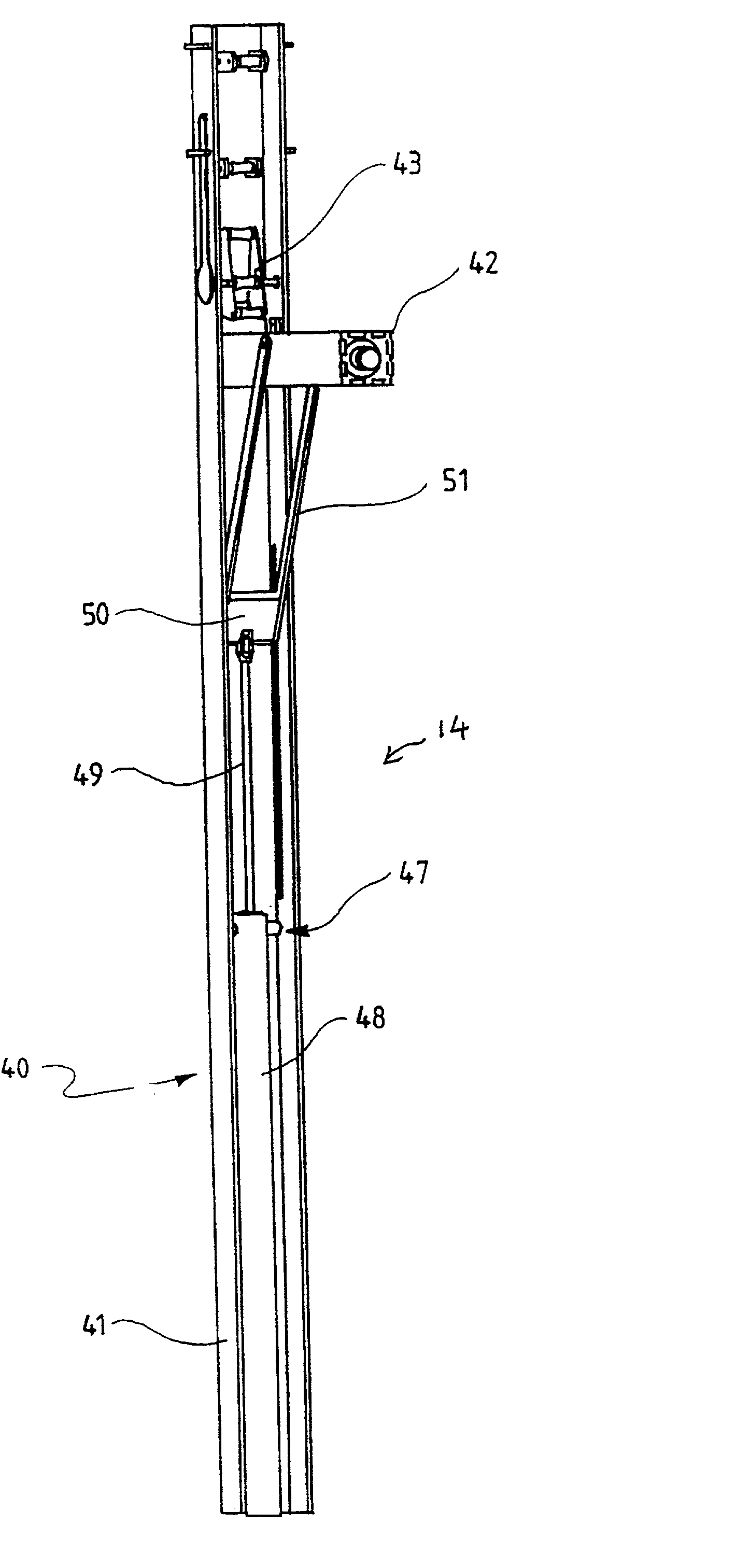
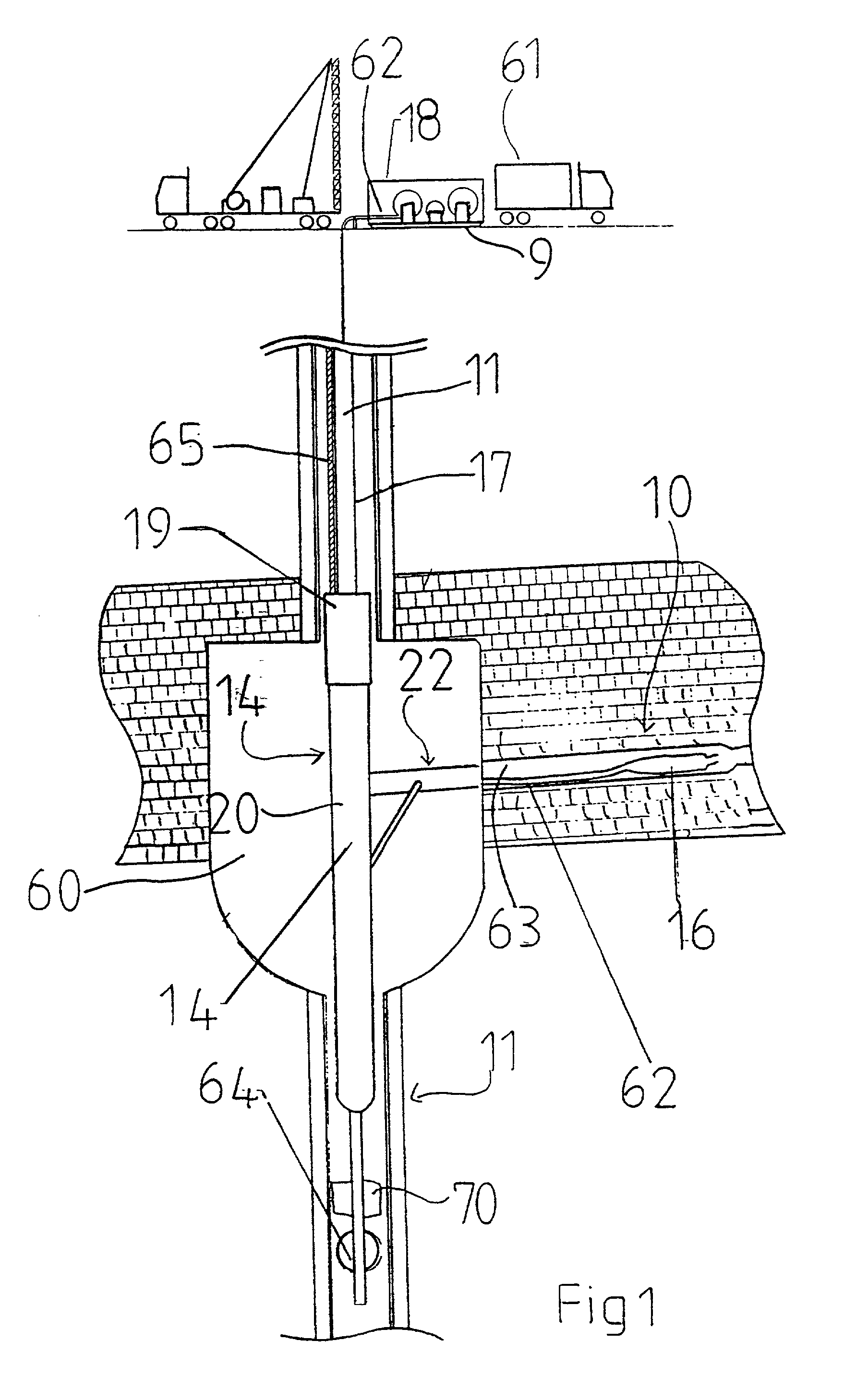
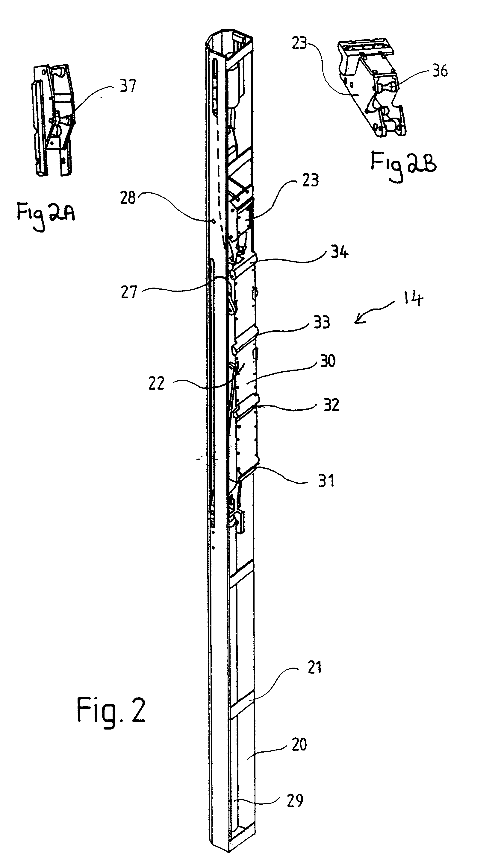
[0062] Referring to the figures, and initially to FIG. 1, there is shown diagrammatically an ultra-short-radius drilling method and assembly for cutting a substantially horizontal bore 63 into a coal seam 10 from an existing vertical borehole 11.

[0063] FIG. 1 shows a vertical bore 11 pre-drilled into the ground and extending through a coal seam 10.

[0064] An assembly 14 is shown in FIG. 1 and which is positioned in a pre-formed slot or cavity 60 in one side of vertical borehole 11.

[0065] A self-advancing steerable fluid cutting device 16 has been positioned substantially horizontally into coal seam 10 by virtue of the assembly 14.

[0066] The self-advancing cutting device 16 has a tubular steel body about 40-80 cm long and 5-15 cm in diameter. The body has a number of rearwardly facing high pressure retro jet thrusters which propel the cutting apparatus in a forward direction. The front face of the cutting device is provided with one or more high pressure water jet cutters to cut the b...


PUM


Abstract

An erectable arm assembly for use in a borehole, the erectable arm assembly comprising a main body and an arm member, the arm member being able to move between a collapsed position in which the assembly can be removed from the borehole and an erected position, the erectable arm assembly being adapted to house a fluid drilling assembly comprising a fluid cutting device and a flexible hose drill string such that the arm member during erection can contain at least part of the fluid drilling assembly, and when in the erected position the arm member is able to guide the fluid cutting device towards the borehole wall, the assembly further including at least one sensor for monitoring the arm member or the fluid drilling assembly.

Description

[0001] This invention relates to an erectable arm assembly for use in boreholes, and particularly relates to an assembly which can direct a fluid cutter into the borehole wall.[0002] Whipstocks are well known in the mining and petroleum industries and are used to change the direction of a drill hole (directional drilling). Since the earliest times, boreholes were made to deviate by placing tapered wedges or "whipstocks" in the borehole to force the bit sideways into a new direction, and it is well known that different bottom-hole assemblies had a tendency either to increase or decrease the inclination of the hole. No one drilling method is satisfactory for all radii of curvature. It is therefore customary to distinguish among these as long-, medium-, short-, and ultra-short-radius methods. The invention relates to ultra-short-radius methods which are typically defined to have a radius of 2 ft. (0.6 m) or less.[0003] Directionally drilled wells fall into two main categories. In the f...

Claims


Application Information

Patent Timeline
Patent Type & Authority Applications(United States)
IPC IPC(8): E21B7/06E21B7/18E21B47/09
CPCE21B7/061E21B47/09E21B7/18
Inventor TRUEMAN, ROBERTMEYER, TIMOTHY GREGORY HAMILTONSTOCKWELL, MATTHEW
Owner TRUEMAN ROBERT
Learn More