
Drive system for imaging device

Active Publication Date: 2011-09-15
MOBIUS IMAGING
View PDF22 Cites 77 Cited by
  • Summary
  • Abstract
  • Description
  • Claims
  • Application Information

AI Technical Summary

Benefits of technology

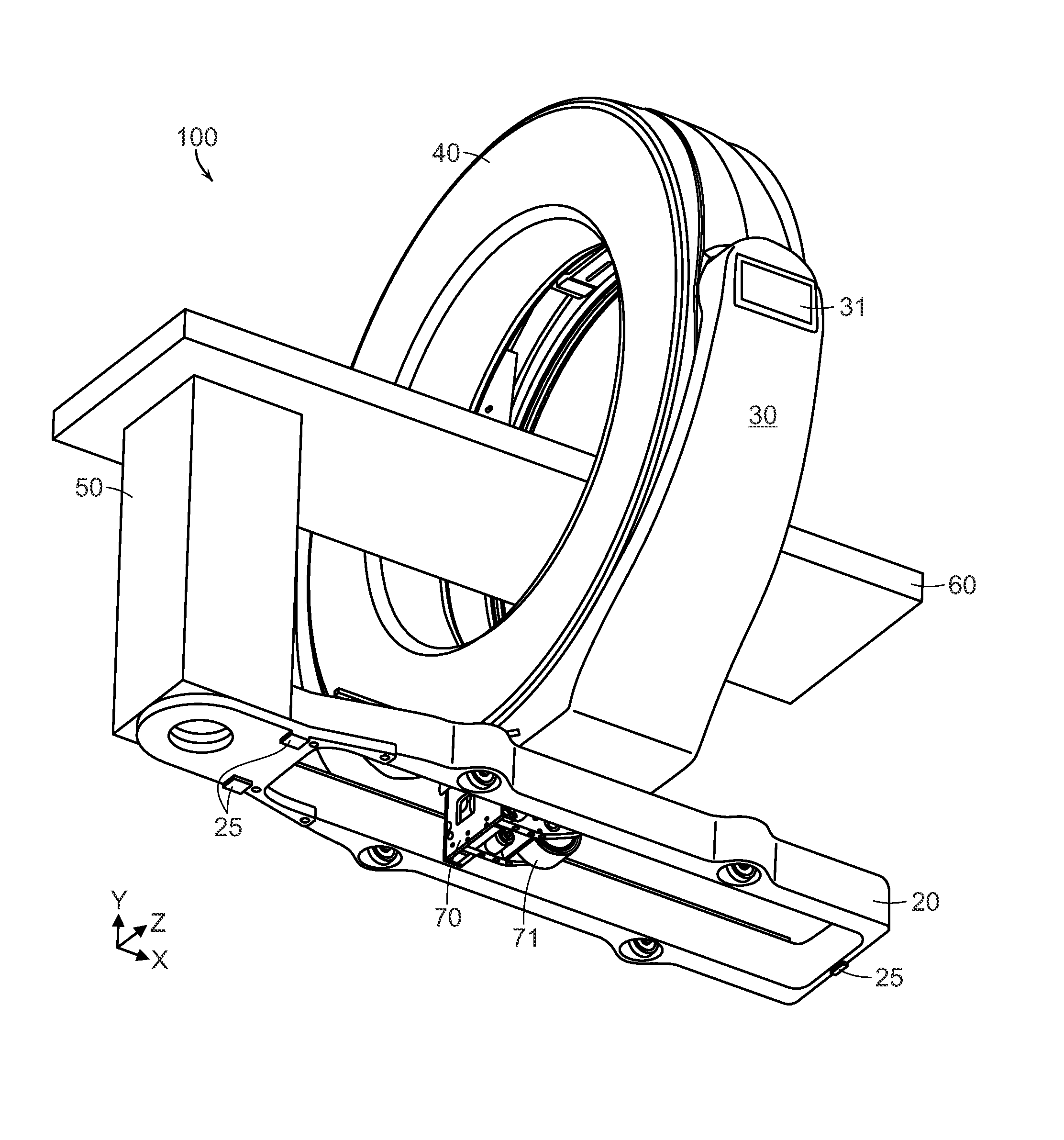
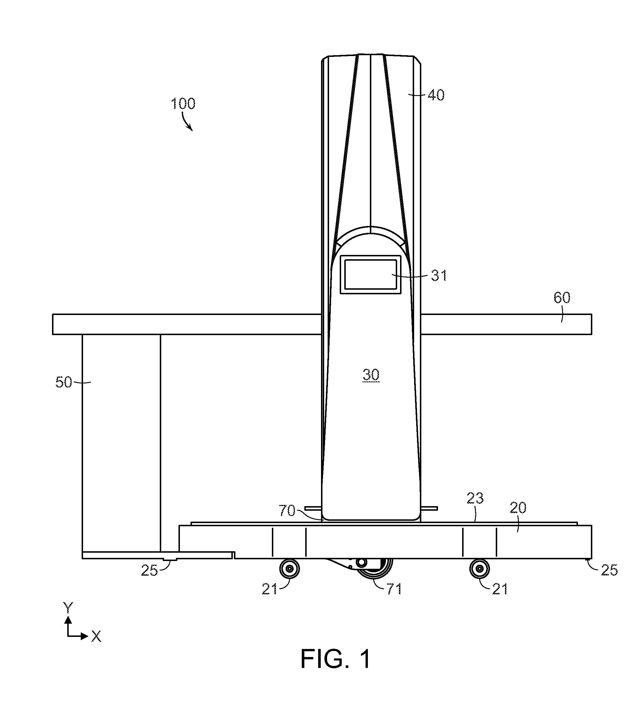
[0008]According to one aspect, the drive wheel supports the weight of the imaging components, but does not directly support the base assembly, which can include a pedestal and tabletop support. One or more casters located on the base can support the weight of the base assembly.
[0009]The drive mechanism can be positioned within the base, preventing interference with a patient table shuttle when driving up to the base and also preventing interference with an operator's feet while standing at the table.
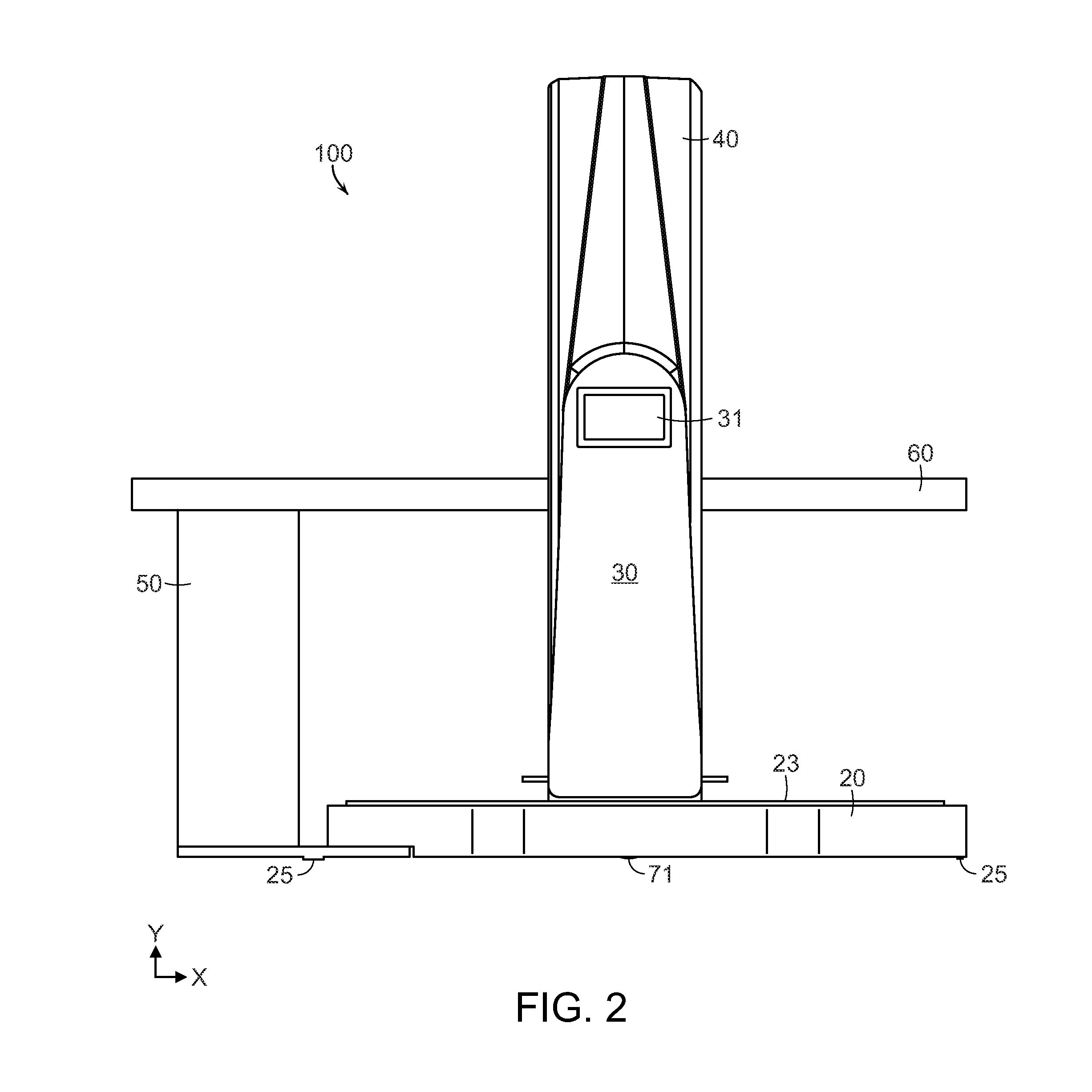
[0010]During scanning, the drive wheel supports the weight of the imaging components, which can be located on a gantry positioned above the drive mechanism. The base is positioned on the floor, on at least three support pads attached to the bottom of the base that define a scanning plane, which minimizes or eliminates deflection of the base during scanning due to an uneven floor surface.
[0012]In one embodiment, the drive wheel is servo controlled and tied to a user drive system on the imaging system, which allows the system to feel weightless during transport.
[0013]In one embodiment, the drive wheel has an active servo-controlled suspension to allow for smooth movement over thresholds, bumps in the floor and ramps when transporting the system.
[0015]In preferred embodiments, the drive mechanism is extremely compact, which allows the entire drive system to be hidden from view, such as beneath the gantry and gimbal assembly and inside the base, while not interfering with operation of the imaging system.

Problems solved by technology

According to one aspect, the drive wheel supports the weight of the imaging components, but does not directly support the base assembly, which can include a pedestal and tabletop support.

Method used


Image

  • Drive system for imaging device
  • Drive system for imaging device
  • Drive system for imaging device

Examples


Embodiment Construction

[0033]This application claims the benefit of U.S. Provisional Application No. 61 / 313,299, filed Mar. 12, 2010, and is related to U.S. application Ser. No. 12 / 576,681, filed Oct. 9, 2009, and to U.S. Provisional Application No. 61 / 315,462, filed Mar. 19, 2010. The entire contents of the above-referenced applications are incorporated herein by reference.

[0034]Referring to FIGS. 1-5, a mobile imaging system 100 according to one embodiment of the invention includes a mobile base 20, a gimbal support 30, a gantry ring 40, and a pedestal 50. The system 100 includes image collection components, such as a rotatable x-ray source and detector array or stationary magnetic resonance imaging components, that are housed within the gantry ring 40. The system 100 is configured to collect imaging data, such as, for example x-ray computed tomography (CT) or magnetic resonance imaging (MRI) data, from an object located within the bore of the gantry ring 40, in any manner known in the medical imaging f...


PUM


Abstract

A drive mechanism for a mobile imaging system comprises a main drive geared into a drive wheel for propelling the imaging system, including a base and one or more imaging components, across a surface. The drive mechanism can also include a scan drive that moves the drive mechanism and the one or more imaging components along an axis relative to the base to provide an imaging scan, and a suspension drive that extends the drive wheel relative to a bottom surface when the imaging system is in a transport mode and retracts the drive wheel relative to the bottom surface of the base when the imaging system is in an imaging mode. The drive wheel supports the weight of the imaging components, but does not directly support the base assembly, which can include pedestal and tabletop support. One or more casters located on the base can support the weight of the base assembly.

Description

CROSS-REFERENCE TO RELATED APPLICATION[0001]This application claims the benefit of U.S. Provisional Application No. 61 / 313,299, filed Mar. 12, 2010, the entire contents of which are incorporated herein by reference.STATEMENT REGARDING FEDERALLY SPONSORED RESEARCH OR DEVELOPMENT[0002]N / ABACKGROUND OF THE INVENTION[0003]Conventional medical imaging devices, such as computed tomography (CT) and magnetic resonance (MR) imaging devices, are typically fixed, immobile devices located in a discrete area reserved for imaging that is often far removed from the point-of-care where the devices could be most useful.[0004]It would be desirable to make these imaging devices mobile, so that they can move to various locations within a hospital or other health services environment. This is difficult due to the size, weight and overall number of components required for making an operable imaging system, and even a relatively small and compact imaging device, such as an x-ray CT scanner, can weigh upwa...

Claims


Application Information

Patent Timeline
Patent Type & Authority Applications(United States)
IPC IPC(8): H05G1/02
CPCA61B6/035A61B6/4405A61B6/4429H04N5/23293G01N2223/308G01N2223/3303G01N2223/301A61B6/4435
Inventor GREGERSON, EUGENE A.STANTON, RUSSELLALLEN, MICHAELCONNOR, MICHAELCOPPEN, SCOTT
Owner MOBIUS IMAGING
Learn More