Headphone device

a headphone and headphone technology, applied in the field of headphones, can solve the problems of unfavorable cost, complicated structure, and sometimes falling off of the headphone unit during the use of the headphone, and achieve the effects of reducing the risk of falling off, and improving the sound quality of the headphone uni

Inactive Publication Date: 2006-03-23
AUDIO-TECHNICA
View PDF1 Cites 76 Cited by
  • Summary
  • Abstract
  • Description
  • Claims
  • Application Information

AI Technical Summary

Benefits of technology

[0017] According to this configuration, since the second arm is connected to the first arm so as to be turnable in a movable range of approximately 90 degrees, the optimum positions of the headphone at the time when the headphone is in use and the time when it is folded and stored can be secured easily.

Problems solved by technology

Therefore, a pressing force toward the ear side, which acts on the headphone unit side via the headband, is weak, so that the headphone unit sometimes slips down or comes off during the use of the headphone.
Accordingly, however, the structure becomes complicated, and this configuration is also unfavorable in terms of cost.
Also, upon mounting the headphone, it is necessary to put the aural hook portion on an auricle after the headband has been mounted on the head, which presents a problem of troublesome mounting operation.

Method used


Image

  • Headphone device
  • Headphone device
  • Headphone device

Examples


Embodiment Construction

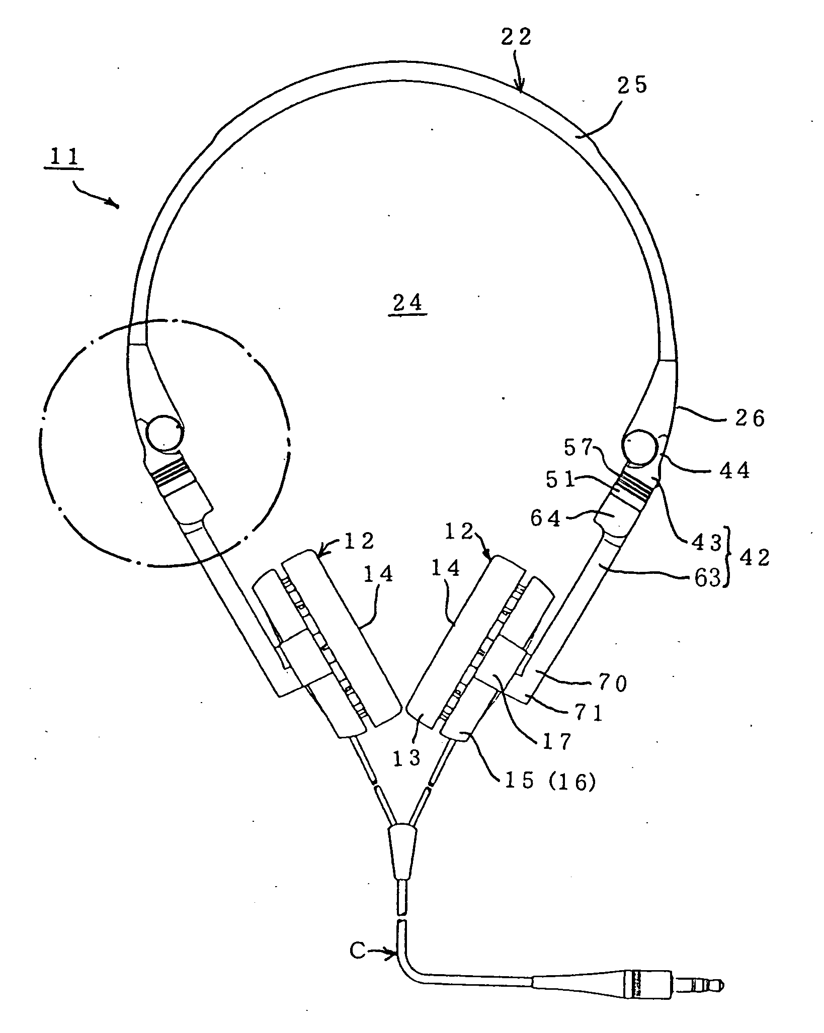
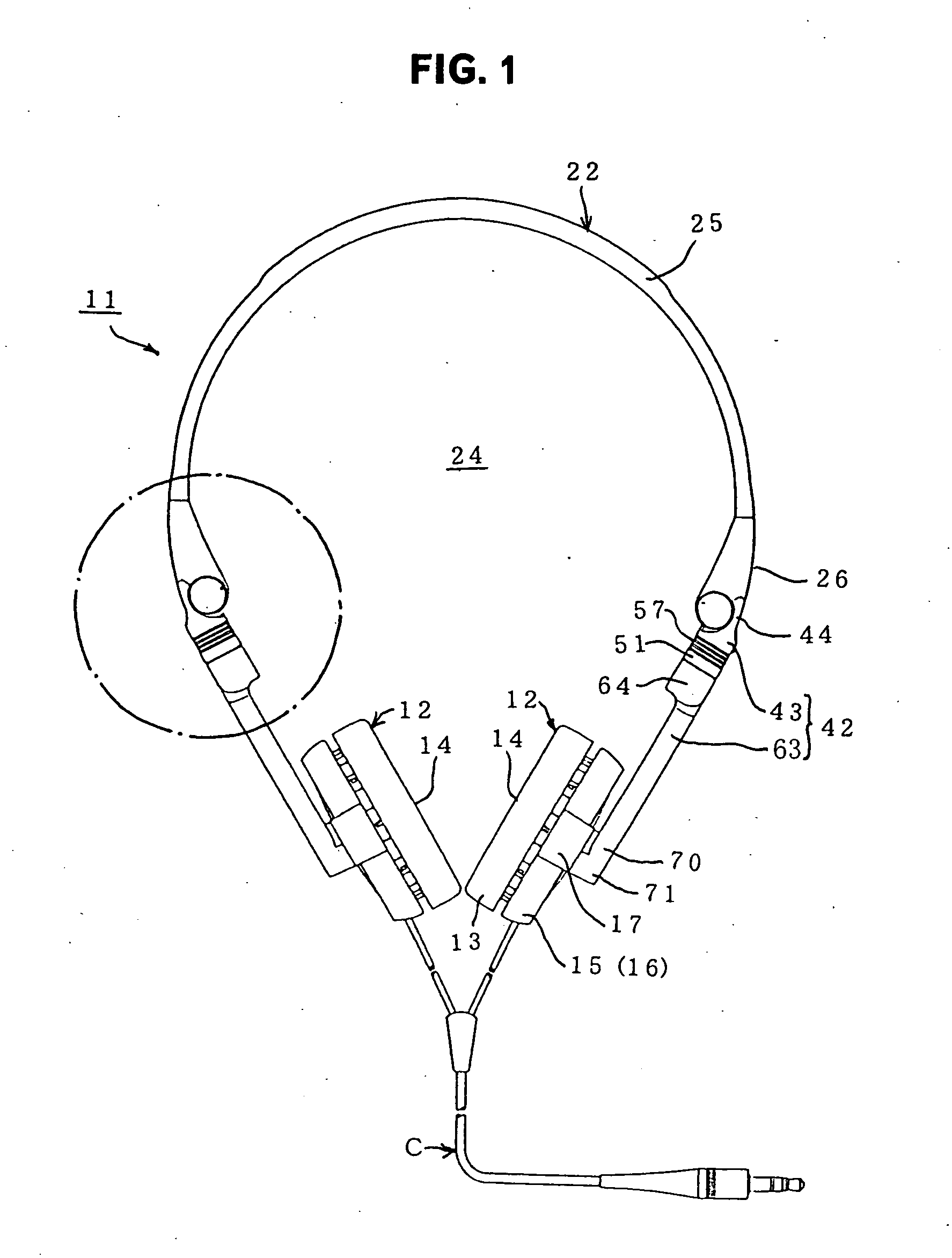
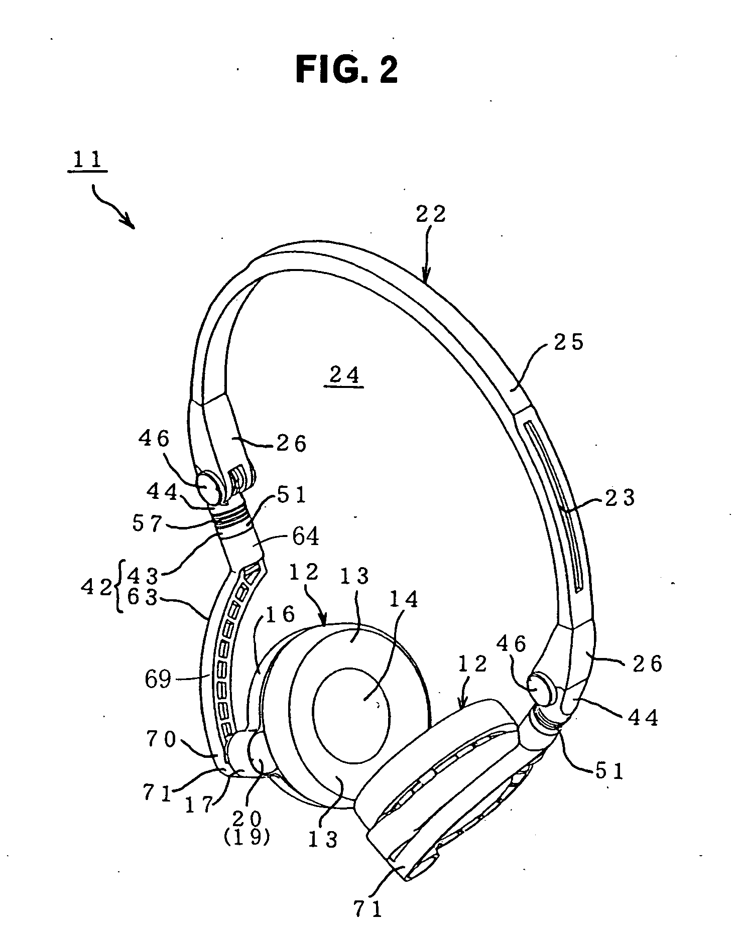
[0028] An embodiment of the present invention will now be described with reference to the accompanying drawings (FIGS. 1 to 8). In these figures, FIG. 1 is a front view showing one example of a headphone in accordance with the present invention, FIG. 2 is a perspective view of the headphone shown in FIG. 1, and FIG. 3 is an enlarged sectional view of a portion encircled by a chain line in FIG. 1.

[0029] Referring to FIGS. 1 to 3, as its basic form, a headphone 11 in accordance with the present invention includes a pair of right and left headphone units 12, 12 and a substantially U-shaped elastic band (headband) 22 which is mounted ranging from the human head's crown to both sides of the head (these are not shown) and supports the headphone units 12, 12 at both ends thereof. Reference character C in FIG. 1 denotes a connection cord.

[0030] The headphone units 12, 12 are supported by the elastic band 22 so as to come into contact with the human body's right and left ears with a proper...


PUM


Abstract

There is provided a headphone which is handy for carrying or storing because of its compactness, and also provides a good sense of mounting. The headphone includes a pair of right and left headphone units 12 and an elastic band 22 formed substantially into a U shape, which is mounted ranging from the human head's crown to both sides of the head, and supports the headphone units 12 in end portions thereof. Between an end part of the elastic band 22 and the headphone unit 12, there is provided a multiaxial arm joint 42 including a first arm 43 one end of which is connected turnably to the end part of the elastic band 22 and a second arm 63 one end of which is connected turnably to the other end of the first arm 43 and the other end of which is connected turnably to the headphone unit 12. By tuning the connecting portions of the multiaxial arm joint 42 the headphone units 12 are housed within an internal space 24 encircled by the elastic band 22.

Description

TECHNICAL FIELD [0001] The present invention relates to a headphone which can be folded in a compact form when being not in use so as to be handy for carrying or storing, and also can provide a good sense of mounting when being mounted for use. BACKGROUND ART [0002] Conventionally, some headphones which can be folded in a compact form when being carried or stored have been proposed as disclosed, for example, in Patent Document 1 (Japanese Patent Application Publication No. 2000-125386). [0003] As its basic form, the headphone includes an elastically deformable headband formed substantially into a U shape, which is mounted ranging from the human head's crown to both sides of the head, and a pair of headphone units supported at both ends of the headband. In the headphone described in the aforementioned Patent Document 1, the headband is made foldable by means of a hinge in a central portion of the headband, and the headphone units are connected to the ends of the headband so as to be ...

Claims


Application Information

Patent Timeline
Patent Type & Authority Applications(United States)
IPC IPC(8): H04R25/00
CPCH04R5/0335H04R1/1066H04R1/10
Inventor TACHIKAWA, YOSHINORI
Owner AUDIO-TECHNICA
Why Eureka
Try Eureka