Arrangement for positioning milking animals in a milking parlour

a technology parlours, which is applied in the field of arrangement for positioning milking animals in milking parlours, can solve the problems of not being able to use such a pair of gates, and the risk of small cows in the herd taking a position

Inactive Publication Date: 2012-10-23
DELAVAL HLDG AB
View PDF19 Cites 2 Cited by
  • Summary
  • Abstract
  • Description
  • Claims
  • Application Information

AI Technical Summary

Benefits of technology

[0007]This object is achieved according to the invention by the feature that the arrangement comprises a power member and motion transmission mechanism adapted to transfer an activating motion from the power member to the individual front positioning elements such that the individual front positioning elements come in contact with front portions of the animals and act with a resilient force on the animals in a manner such that they step backwards to a desired milking position in the milking stalls in which the rear parts of the animals are in contact with the second positioning element. The resilient force from the individual front positioning elements has a magnitude which results in that the cows step backwards to the second positioning element. On the other hand, the magnitude of the resilient force will not be too large such as to cause stress on the animals. Normally, a short animal has to step a larger distance back to the second positioning element than a long animal. The existence of the individual front positioning elements enable a gentle pushing of especially short animals to a desired milking position in the milking stall. In the desired milking position, the udders of the cows are easily reachable for an operator attaching milking members to the milking animals in the milking stalls.
[0009]According to a preferred embodiment of the invention, the motion transmission mechanism comprises at least one spring member which transmits the force from the power member to the resilient force by which the individual front positioning elements act on the animals. By the use of a spring member in the motion transmission mechanism, the individual front positioning elements can be given suitable resilient properties in a relatively simple manner. The motion transmission mechanism may comprise a displaceable rod element connected to the power member. The power member can displace such a rod element between an active position in which the individual front positioning elements act on the animals in the milking stalls and a non-active position in which the individual front positioning elements are in a retracted position in the milking stalls. The rod element may be arranged in parallel to said vertical plane of the front barrier. Preferably, the rod element is arranged in said vertical plane or at a relatively small distance from said vertical plane in order to reduce the length of the motion transmission mechanism.
[0010]According to a further embodiment of the invention, said spring member is a helical spring arranged around the displaceable rod element. The above mentioned positioning of the helical spring enables the arrangement to be made relatively compact. However, it is possible to use other kinds of spring members in the motion transmission mechanism. Preferably, a first end of the helical spring is connected to an element fixedly connected to the rod element and a second end of the helical spring is connected to an element movably connected to the rod element. Such a mounting of the helical spring results in that the components of the motion transmission mechanism, which are connected to the second end of the helical spring, obtain resilient properties.
[0013]According to a further embodiment of the invention, the power member is a pneumatic or a hydraulic cylinder. It is easy to initiate a motion to the motion transmission mechanism and the front positioning element by means of such a cylinder. However, it is possible to use other kinds of power member. Preferably, the second positioning element is a rump rail having a contact surface perpendicular to the longitudinal axis of the animals. Such a contact surface ensures that the rear parts of the animals are held in a relatively fixed position when the animals are in a milking position.

Problems solved by technology

Due to the fact that milking stalls are equally large and the cows in a herd have different sizes, there is a risk that small cows of the herd take a position in the milking stalls in which the udders of the cows are located at a relatively long distance from the pit.
However, it is not possible to use such a pair of gates when the animals stand in an inclined position in relation to the front part of the milking stalls.

Method used


Image

  • Arrangement for positioning milking animals in a milking parlour
  • Arrangement for positioning milking animals in a milking parlour
  • Arrangement for positioning milking animals in a milking parlour

Examples


Embodiment Construction

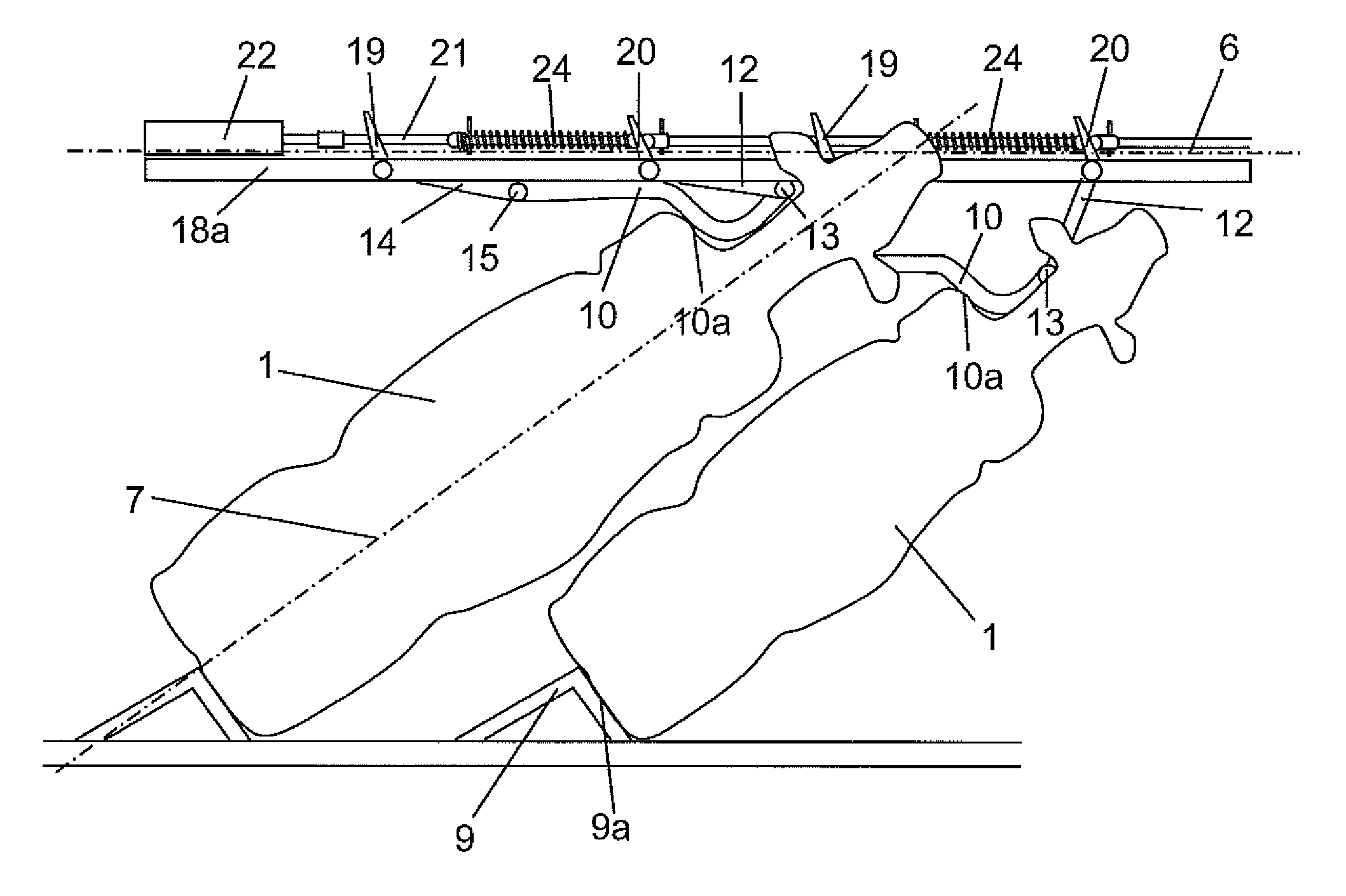
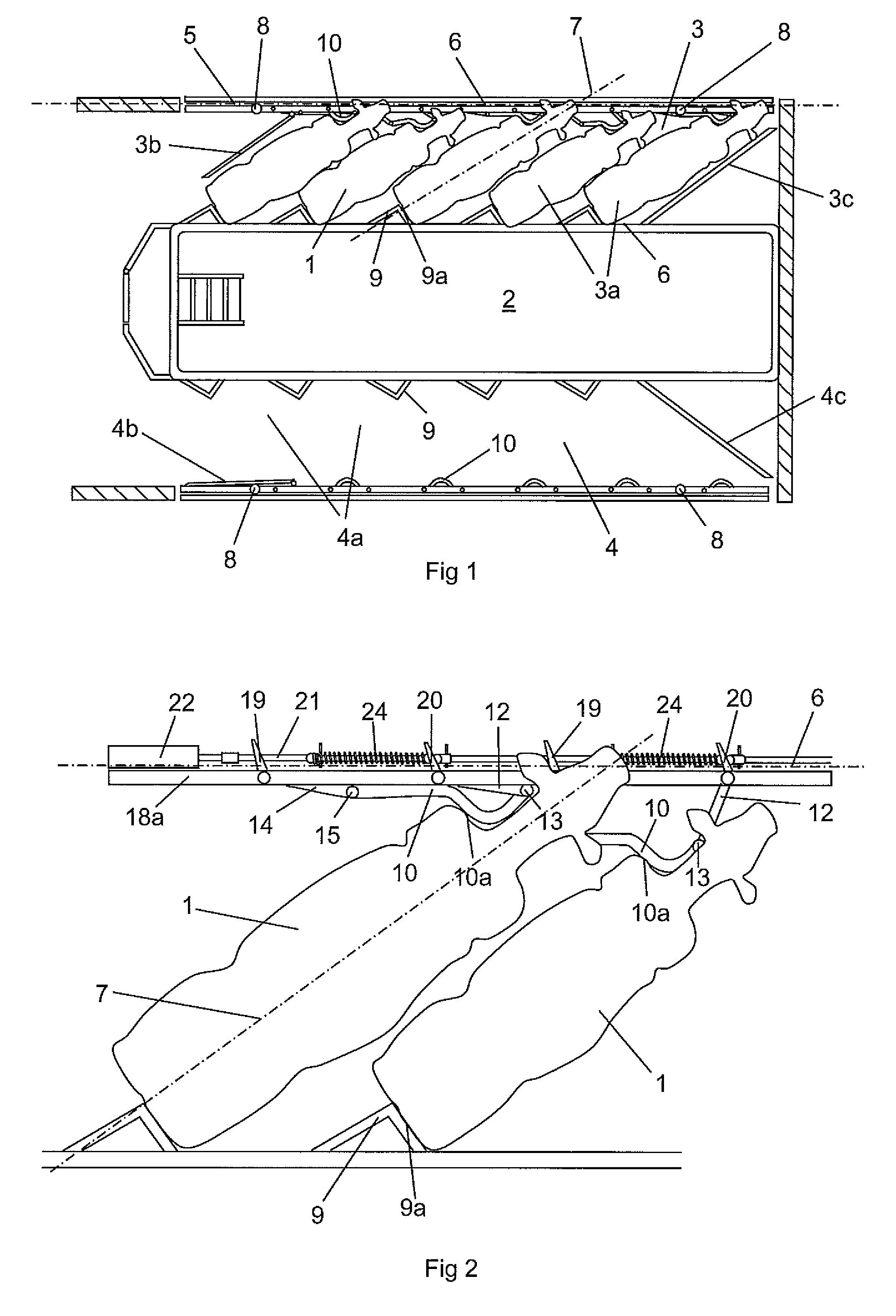
[0020]FIG. 1 shows a herringbone milking parlour for milking of cows 1. The parlour comprises a centrally located pit 2 in which at least one operator works. A first group of milking stalls 3 is located on one side of the pit 1 and a second group of milking stalls 4 is located on an opposite side of the pit 2. In this case, each group 3, 4 comprises five milking stalls 3a, 4a. A first entrance gate 3b to the first group of milking stalls 3 is pivotably arranged between an open position and a closed position. A fence element 3c defines an inclined side wall of the first group of milking stalls 3. When the entrance gate 3b is moved to a closed position, it defines an opposite inclined side wall of the first group of milking stalls 3. In a corresponding manner, a second entrance gate 4b to the second group of milking stalls 4 is pivotably arranged between an open position and a closed position. A fence element 4c defines an inclined side wall of the second group of milking stalls 4. Wh...


PUM


Abstract

An arrangement for positioning at least two milking animals in at least two milking stalls allows the animals to stand in an inclined position such that a longitudinal axis of the animals forms an angle of 10°-80° to a vertical plane (6) of a front barrier (5) of the milking stalls. The arrangement includes a power member (22) and motion transmission mechanism adapted to transfer an activating motion from the power member to individual front positioning elements (10) in the milking stalls such that the individual front positioning element in each milking stall comes in contact with a front portion of the animal and acts with a resilient force on the animal in a manner such that the animal steps backwards to a desired milking position in which the rear part of the animal is in contact with a second rear positioning element (9).

Description

BACKGROUND OF THE INVENTION AND PRIOR ART[0001]The present invention relates to an arrangement for positioning at least two milking animals in at least two milking stalls, wherein the arrangement comprises a front barrier arranged in a vertical plane and defining a front portion of the milking stalls, positioning means adapted to position the animals in a milking position in the milking stalls such that a longitudinal axis of the animals forms an angle of 10°-80° to said vertical plane of the front barrier and wherein said positioning means comprise an individually movable front positioning element in each milking stall, adapted to define the position of a front part of the animal in the milking stall, and a second positioning element adapted to define the position of a rear portion of the milking stalls.[0002]Milking parlors having a plurality of milking stalls are usually provided with a pit from which an operator attaches milking members to cows in the milking stalls. It is impor...

Claims


Application Information

Patent Timeline
Patent Type & Authority Patents(United States)
IPC IPC(8): A01J5/00
CPCA01K1/12A01K1/123
Inventor LEYRIT, JEAN-PIERRE
Owner DELAVAL HLDG AB
Why Eureka
Try Eureka