Measuring tube for magneto-inductive flow-measuring systems

Active Publication Date: 2017-01-03
KRONE GMBH
View PDF24 Cites 1 Cited by
  • Summary
  • Abstract
  • Description
  • Claims
  • Application Information

AI Technical Summary

Benefits of technology

[0017]The measuring tube according to the invention in which the above derived and described object is met is initially and essentially characterized in that the measuring contacts of the measuring electrodes are provided on the measuring tube in such a manner and the counter contacts corresponding to the measuring contacts of the measuring electrodes are arranged in the measuring system in such a manner that the measuring contacts can be brought into electrical contact with the counter contacts by means of an essentially translational movement essentially perpendicular to the direction of the magnetic field. This teaching according to the invention is advantageous for the first design described above of the magneto-inductive flow-measuring system, in which the measuring tube, on the one hand, and the magnetic field generator, on the other hand, are initially separate components that first result in a functional magneto-inductive flow-measuring system when they are brought into function with one another as well as advantageous for the second design, in which the measuring tube, on the one hand, and the magnetic field generator, on the other hand, are components of an already functional magneto-inductive flow-measuring system from the factory. In both cases, it is implemented, in particular, that each of the two measuring contacts of the measuring tube, which have to be initially provided for function, on the one hand, on one side of the measuring tube and, on the other hand, on the other side of the measuring tube, are easily reachable from one side by the corresponding counter contact or can be brought into electro-conductive contact with the corresponding counter contact.
[0023]In a magneto-inductive flow-measuring system, for which the measuring tubes according to the invention are intended, each of the two counter contacts can be assigned a test contact in the second functional unit. Thereby, both test contacts, on the one hand, and both measuring contacts of the measuring tube, on the other hand, are designed and arranged in such a manner that the test contacts have electro-conductive contact to the assigned counter contacts when and only when the counter contact also has electro-conductive contact to the assigned measuring contacts. For this design of magneto-inductive flow-measuring systems, the measuring tube is designed in such a manner that each of the measuring contacts has a test counter contact galvanically connected to it. This can be implemented in a simple manner in that each of the two test counter contacts and the assigned measuring contact are integrally formed.
[0025]Measuring tubes with differing flow cross-sections, i.e., with differing inner diameters, can be easily used when the differing measuring tubes each have the same outer diameter and the same measuring contacts, i.e., only in respect to the flow cross-sections, which means only the inner diameters are different.

Problems solved by technology

A problem results, which is described above, in that one measuring electrode with its measuring contact (and corresponding counter contact) is located on one side of the measuring tube and the other measuring electrode with its measuring contact (and corresponding counter contact) is located on the other side of the measuring tube.

Method used


Image

  • Measuring tube for magneto-inductive flow-measuring systems
  • Measuring tube for magneto-inductive flow-measuring systems
  • Measuring tube for magneto-inductive flow-measuring systems

Examples


Embodiment Construction

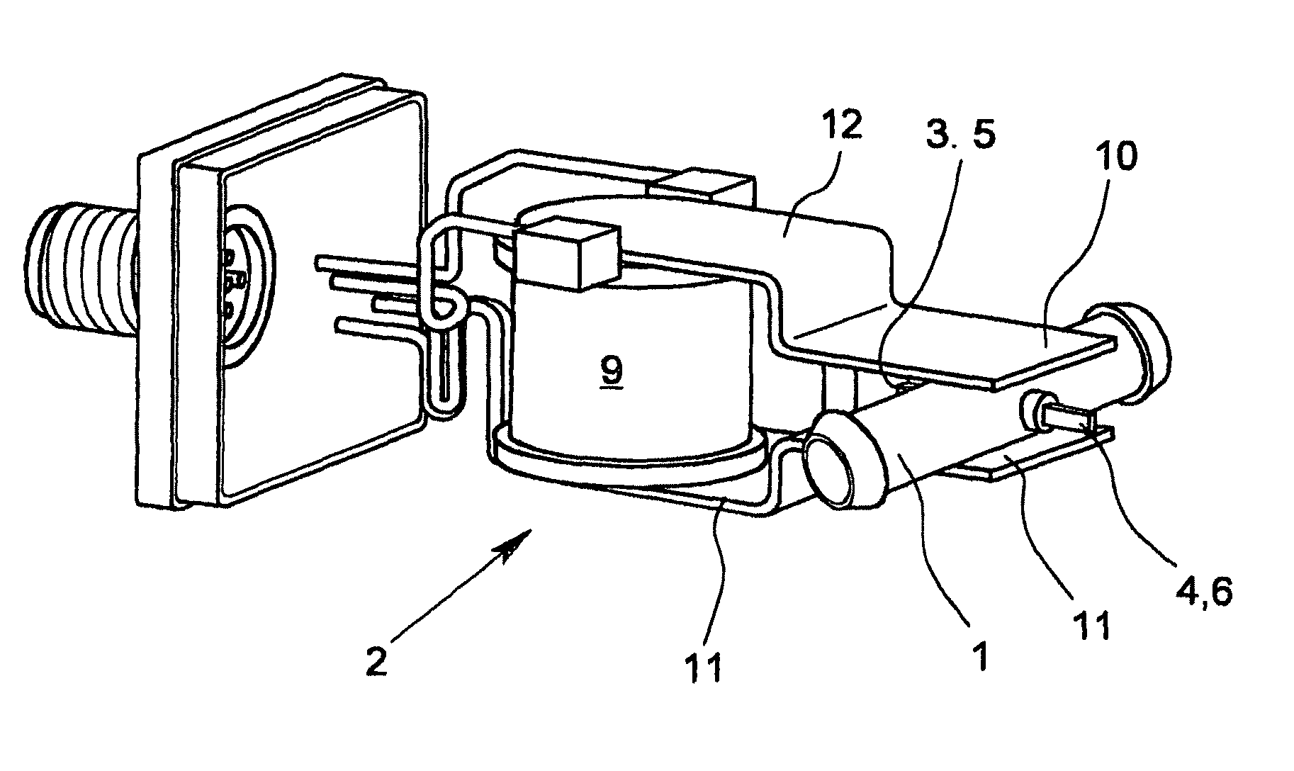
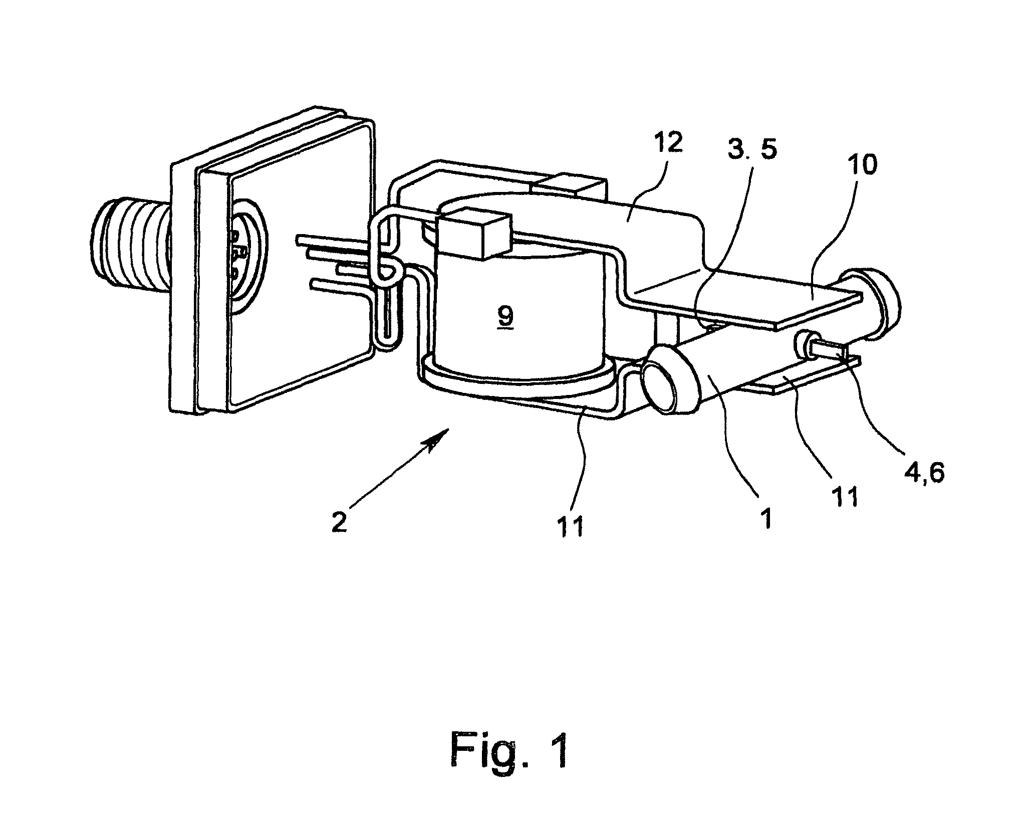
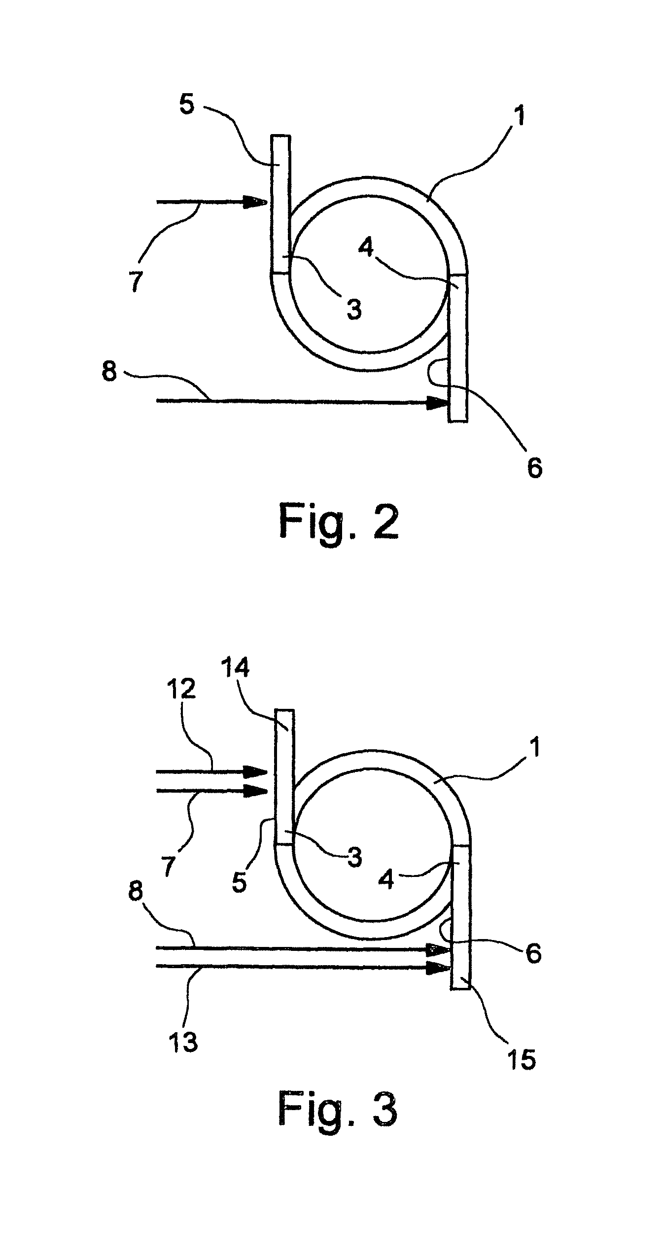
[0034]Initially and essentially, a measuring tube 1 for the flow of an electrically conductive medium and a magnetic field generator 2 for generating a, preferably alternating, magnetic field running at least also perpendicular to the longitudinal axis of the measuring tube 1 and two measuring electrodes 3, 4 preferably in contact with the medium, tapping measuring voltage induced in the electro-conductive medium belong to the magneto-inductive flow-measuring system only schematically shown in FIGS. 1, 4 and 5, wherein the measuring electrodes 3, 4 have measuring contacts 5, 6 accessible on the outside of the measuring tube 1.

[0035]An evaluation unit and a measuring system housing are basically also part of the magneto-inductive flow-measuring system according to the invention. The evaluation unit (not shown) can be a part of a magneto-inductive flow-measuring system, or the evaluation unit can be implemented as a separate component.

[0036]The measuring tube 1 according to the invent...


PUM


Abstract

A measuring tube for magneto-inductive flowmeter systems, having a measuring tube for the flow of an electrically conductive medium and a magnetic field generating device for generating a magnetic field, at least two measuring electrodes which tap the measurement voltage induced in the electrically conductive medium and preferably an evaluation unit. The measuring electrodes have externally accessible measuring contacts, wherein the measuring tube forms a first functional unit with the measuring electrodes, and mating contacts corresponding to the measuring contacts of the measuring electrodes, the magnetic field generating device and an evaluation unit, if present, form a second functional unit. The measuring contacts of the measuring electrodes are provided on the measuring tube in such a manner that they can be brought into electrically conductive contact with the mating contacts by a movement which runs substantially perpendicular to the direction of the magnetic field and is substantially only translational.

Description

BACKGROUND OF THE INVENTION[0001]Field of the Invention[0002]The invention relates to a measuring tube for a magneto-inductive flow measuring system, wherein the flow measuring system has the measuring tube for the flow of an electrically conductive medium and a magnetic field generator for generating a, preferably alternating, magnetic field running at least also perpendicular to the longitudinal axis of the measuring tube, at least two measuring electrodes tapping the measuring voltage induced in the electrically conductive medium, preferably in contact with the medium and preferably an evaluation unit, wherein the measuring electrodes have accessible measuring contacts on the outside of the measuring tube and the measuring tube with the measuring electrodes forming a first functional unit and counter contacts corresponding to the measuring contacts of the measuring electrodes, the magnetic field generator and the evaluation unit (insofar such is present) forming a second function...

Claims


Application Information

Patent Timeline
Patent Type & Authority Patents(United States)
IPC IPC(8): G01F1/58
CPCG01F1/584
Inventor PERFETTI, CHRISTINENEVEN, JOSEF
Owner KRONE GMBH
Why Eureka
Try Eureka