Printing machine

a technology of barrier plate and printing plate, which is applied in the field of printing machine, can solve the problems of troublesome adjustment and long time requirements, and achieve the effects of reducing time requirements, simplifying the replacement procedure, and simplifying the replacement process

Active Publication Date: 2012-11-06
I MAR PLANNING INC
View PDF28 Cites 1 Cited by
  • Summary
  • Abstract
  • Description
  • Claims
  • Application Information

AI Technical Summary

Benefits of technology

[0060]According to the printing machine of claim 1, the replacement procedure is considerably automated, whereby significant simplification of the replacement procedure and reduction in time required for the replacement procedure are achieved, as described above.
[0061]According to the printing machine of claim 2, the deviation of the position of the barrier plate during printing is small or more or less eliminated, as described above.
[0062]According to the printing machine of claim 3, automation of replacement of the pair of barrier plates is simplified.
[0063]According to the printing machine of claim 4, the cover for covering the upper part of the ink fountain roller and the barrier plate stopper do not need to be separately arranged.
[0064]According to the printing machine of claim 5, the size of the ink channel is easily changed by simply turning the ink fountain member and changing the work position, as described above.
[0065]According to the printing machine of claim 6, the level of ink in the ink fountain is maintained substantially constant and the amount of ink to be placed in the ink fountain is reduced during printing, whereby the ink in the ink fountain is prevented from deteriorating and adversely affecting the printing quality, and furthermore, the amount of ink that becomes a waste in time of replacement is reduced and the time required for collecting the remaining ink is reduced, as described above.

Problems solved by technology

In the conventional printing machine, the vibrating roller and the ink distributing roller are automatically cleaned by a so-called inker cleaning, but the ink fountain roller and the ink fountain member are cleaned manually in the following manner since automation of cleaning is difficult to perform thereon.
Thus, the collecting old ink and the cleaning works are troublesome, and furthermore, the replacement procedure requires time since the ink fountain member and the ink fountain roller must be cleaned by hand, whereby a long time is required until the next printing can be started.
Furthermore, the size (width) of the ink channel sometimes needs to be changed depending on the content of printing, in which case, the size of the ink channel is adjusted by changing the position or the angle of the ink fountain member in the prior art, but such adjustment is also troublesome.

Method used


Image

  • Printing machine
  • Printing machine
  • Printing machine

Examples


Embodiment Construction

[0128]The embodiment of the present invention will now be described with reference to the drawings.

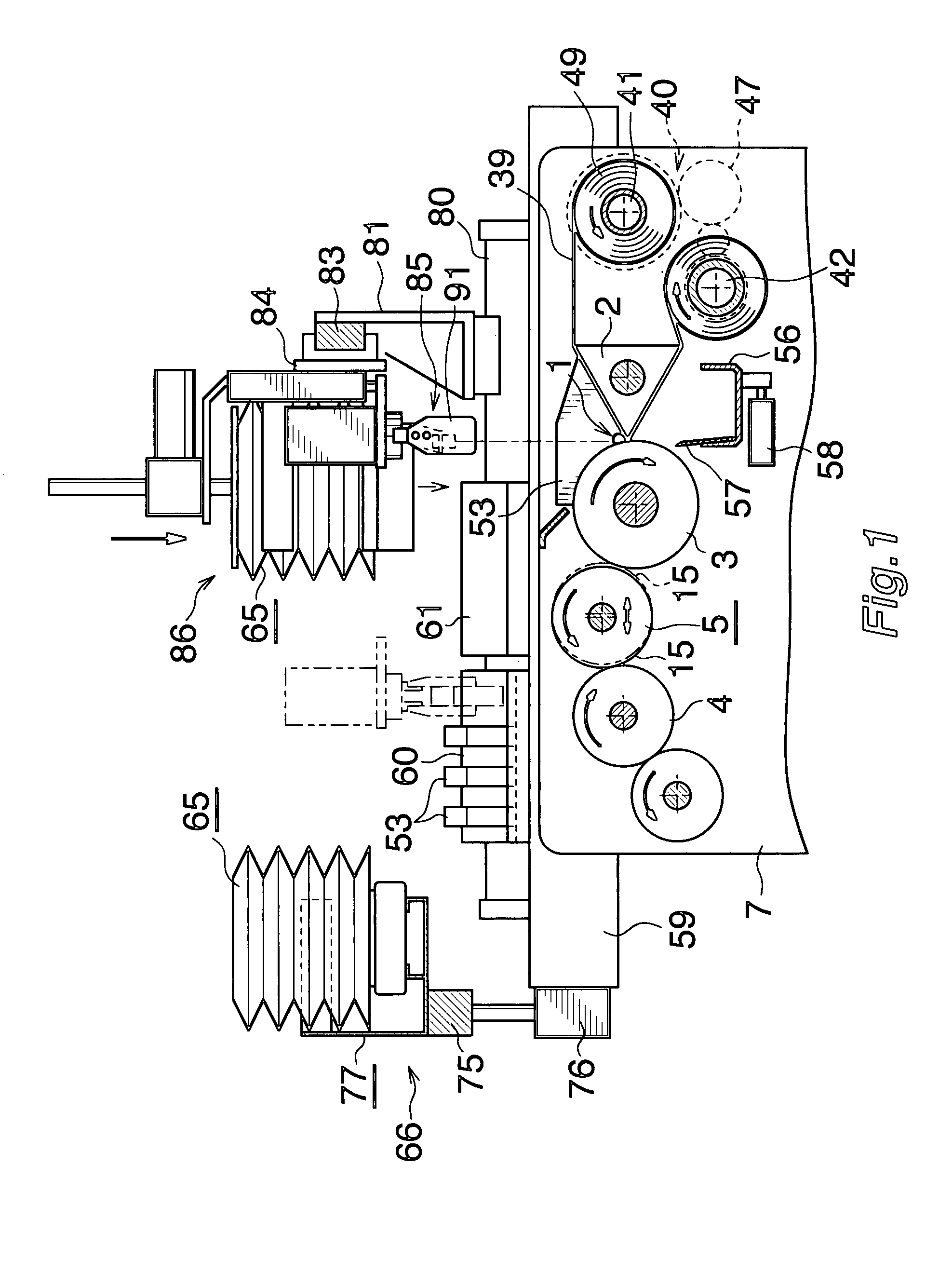
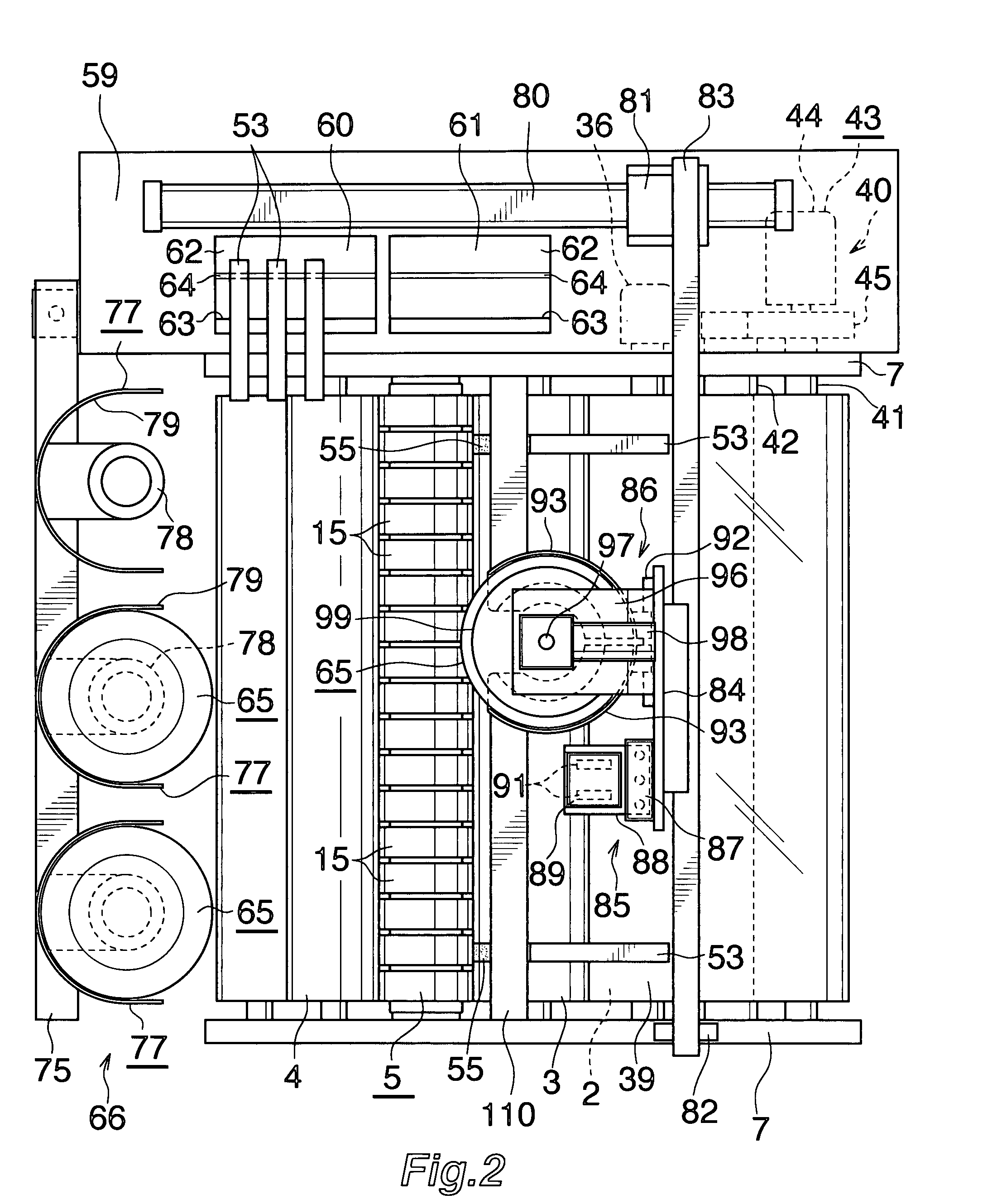
[0129]FIG. 1 is a left side view schematically showing one part of an inking arrangement of the printing machine, and FIG. 2 is a plane view of the same. In the following description, the right side of FIGS. 1 and 2 is the front, the left side is the back, and the right and left sides when seen from the front is the right and the left.

[0130]In FIGS. 1 and 2, a first ink distributing roller (4) of the plurality of ink distributing rollers is arranged behind an ink fountain roller (3) close to the back end of an ink fountain member (2) forming an ink fountain (1), and a unit (5) of a plurality of divided vibrating rollers is arranged between the fountain roller (3) and the distributing roller (4). The axes of the fountain roller (3) and the distributing roller (4) are parallel to each other and extend in the right-left direction. The fountain roller (3) and the distributing roller (4) ar...


PUM


Abstract

A printing machine in which substantial automation of the replacement procedure is achieved, and thus significant simplification of replacement procedure, and reduction of time required for the procedure are achieved is provided. The printing machine comprises an ink fountain member 2, an ink fountain roller 3, a strip of sheet 39 of which middle part is placed over the ink fountain member 2, a sheet moving device 40, a pair of barrier plates 53 attracted to the ink fountain member 2 under the sheet 39 and attracted to the outer peripheral surface of the ink fountain roller 3 by a permanent magnet, a cleaning tank 56, a cleaning blade 57, a reciprocating device 58, a barrier plate replacing device 85, a plurality of ink containers 65 accommodating different types of ink and being stored in a container storage unit 66, and an ink supply device 86 for holding the desired ink container 65 and supplying the ink therein to the ink fountain 1.

Description

CROSS REFERENCE TO RELATED APPLICATIONS[0001]This application is related to three co-pending applications: “UNIT OF A PLURALITY OF DIVIDED VIBRATING ROLLERS AND PRINTING MACHINE” filed even date herewith in the names of Masayuki Izume as a national phase entry of PCT / JP2006 / 306428; “PRINTING MACHINE” filed even date herewith in the name of Masayuki Izume as a national phase entry of PCT / JP2006 / 306430; and “PRINTING MACHINE” filed even date herewith in the name of Masayuki Izume as a national phase entry of PCT / JP2006 / 306434; which applications are assigned to the assignee of the present application and all three incorporated by reference herein.TECHNICAL FIELD[0002]The present invention relates to a printing machine.BACKGROUND ART[0003]In the usual printing machine, an ink fountain roller is arranged close to an ink fountain member forming an ink fountain, ink applied to the outer peripheral surface of the ink fountain roller from the ink fountain is transferred to an ink distributi...

Claims


Application Information

Patent Timeline
Patent Type & Authority Patents(United States)
IPC IPC(8): B41F31/06B41F31/02
CPCB41F31/02B41F31/04B41F31/14
Inventor IZUME, MASAYUKI
Owner I MAR PLANNING INC
Why Eureka
Try Eureka