Magnetic light fitting

A technology of light bulbs and magnets, applied in connection, discharge lamps, incandescent lamps, etc., can solve the problems of easy injury of light bulbs, troublesome replacement of light bulbs, and low manual dexterity of users, so as to achieve more efficient work, reduce the risk of electric shock, and improve the quality of life Effect

Inactive Publication Date: 2008-09-24
THE MAGNETIC CONNECTION CO LTD
View PDF0 Cites 0 Cited by
  • Summary
  • Abstract
  • Description
  • Claims
  • Application Information

AI Technical Summary

Problems solved by technology

This can be especially inconvenient in situations where the bulb is too high to reach or where the user has low manual dexterity
Elderly or high-risk groups are vulnerable to injury when changing light bulbs
In these cases, replacing the bulb in the usual way is cumbersome

Method used


Image

  • Magnetic light fitting
  • Magnetic light fitting
  • Magnetic light fitting

Examples


Embodiment Construction

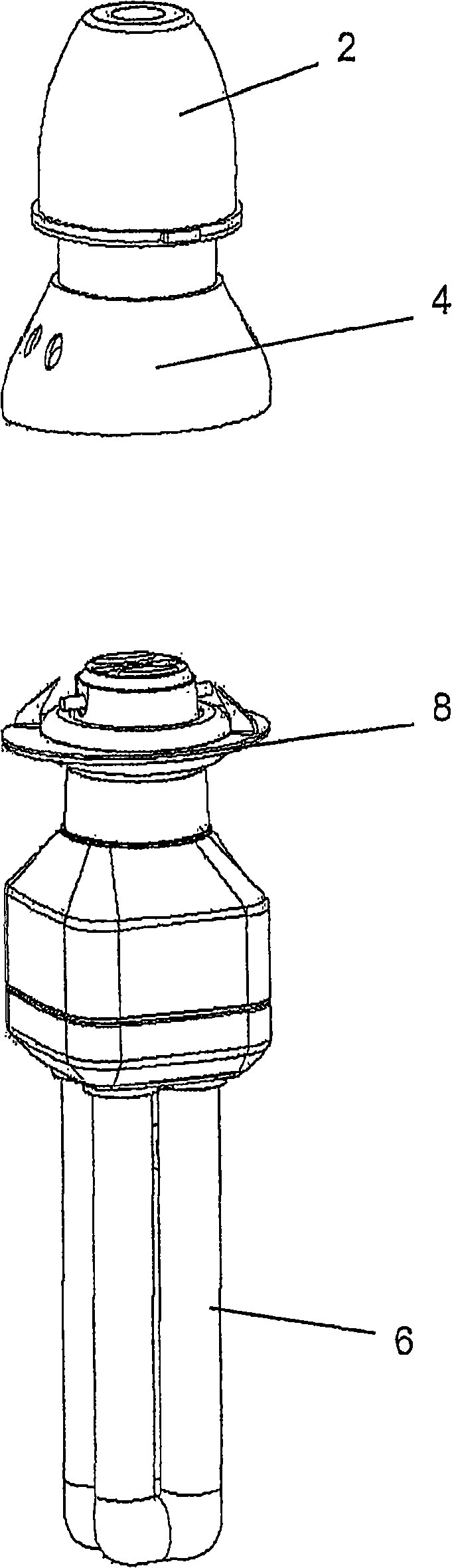
[0037] see first figure 1 , which shows the bulb and socket assembly. A typical lamp fitting 2 is provided with a socket 4 which is shown attached to the lamp fitting 2 . The bulb 6 is shown with a collar part 8 arranged on top. In the illustrated embodiment, the illustrated bulb 6 is a low energy bulb with a bayonet connector.

[0038] The collar part 8 is designed to be received by the socket part 4 in order to retain the bulb 6 in the lamp connection 2 . The detailed main features of the socket part 4 and the collar part 2 will be described with reference to the remaining figures.

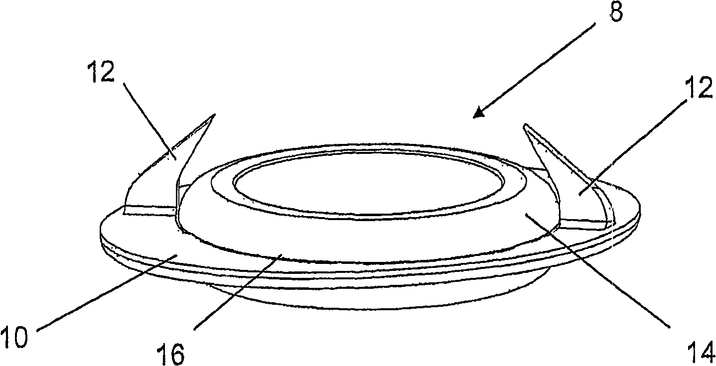
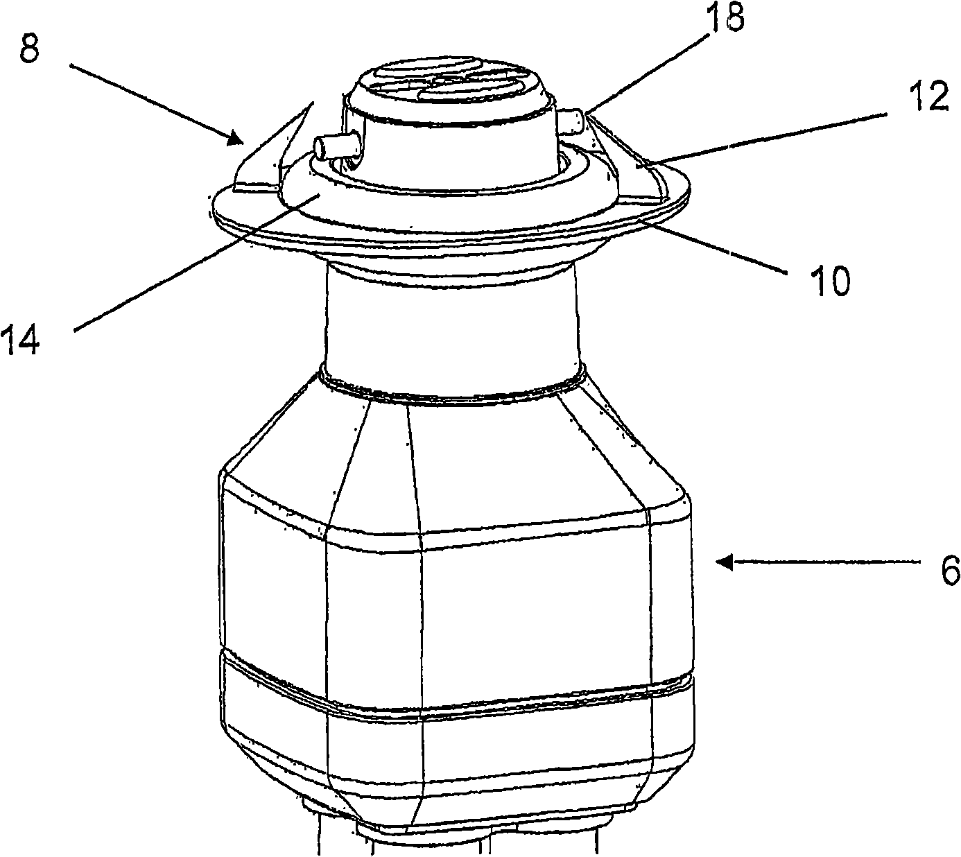
[0039] available at figure 2See collar part 8 alone in . The collar part 8 comprises a flat ring 10 on the top surface of which are provided two fins 12 . The outer edge of the flat ring 10 is oval, while the inner edge is substantially circular. On the inner edge of the flat ring 10 is a rubber ring 14 . The rubber ring 14 is substantially circular and is provided with circumferential ...


PUM


Abstract

The present invention relates to magnetic light fitting, particularly, but not exclusively for domestic and commercial applications. An assembly is provided with first and second parts (8,4), the first part being configured to receive a light bulb (2). A magnetic force is employed to maintain the first part (8) in the second part (4), with guide means also provided to further simplify replacement of a light bulb (2).

Description

technical field [0001] This invention relates to magnetic light fittings, particularly, but not exclusively, to magnetic light fittings for use in domestic and commercial applications. Background technique [0002] Currently, light bulb connectors are widely used in domestic and commercial applications. However, there are many types of bulb connectors, ranging from relatively complex and expensive bulb connectors to standard and relatively inexpensive bulb connectors. It will be appreciated that light bulbs are consumable items that must be replaced periodically. This may be particularly inconvenient in situations where the bulb is too high to reach or where the user has low manual dexterity. Elderly or high-risk groups are vulnerable to injury when changing bulbs. In these situations, changing the bulb in the conventional manner is cumbersome. Contents of the invention [0003] It is an object of the present invention to provide an improved lamp connector which simpli...

Claims


Application Information

Patent Timeline
Patent Type & Authority Applications(China)
IPC IPC(8): H01R33/94H01R13/62H01R13/625H01R33/08
CPCH01R13/625H01R33/0809H01R33/94H01R13/6205
Inventor A·G·E·克洛夫
Owner THE MAGNETIC CONNECTION CO LTD
Why Eureka
Try Eureka