Supercharge Your Innovation With Domain-Expert AI Agents!

Image processing device and method for controlling the same

a technology of image processing and image, applied in the field of image processing devices, can solve the problems of blur in the object image that may vary, and achieve the effect of efficient correction of blur

Active Publication Date: 2013-01-29
CANON KK
View PDF7 Cites 0 Cited by
  • Summary
  • Abstract
  • Description
  • Claims
  • Application Information

AI Technical Summary

Benefits of technology

This approach effectively corrects image blur without causing noticeable positional offsets between regions, maintaining image quality and reducing computational overhead.

Problems solved by technology

Also, when the imaging device is moved, the amount of blur in the object image may vary depending on the position in the image because of the difference in distance between the imaging device and the object.
However, when an image is corrected by applying different correction amounts to different regions as in Japanese Patent Laid-Open No. 2009-258868, the following problem may arise.

Method used


Image

  • Image processing device and method for controlling the same
  • Image processing device and method for controlling the same
  • Image processing device and method for controlling the same

Examples


first embodiment

[0026](First Embodiment)

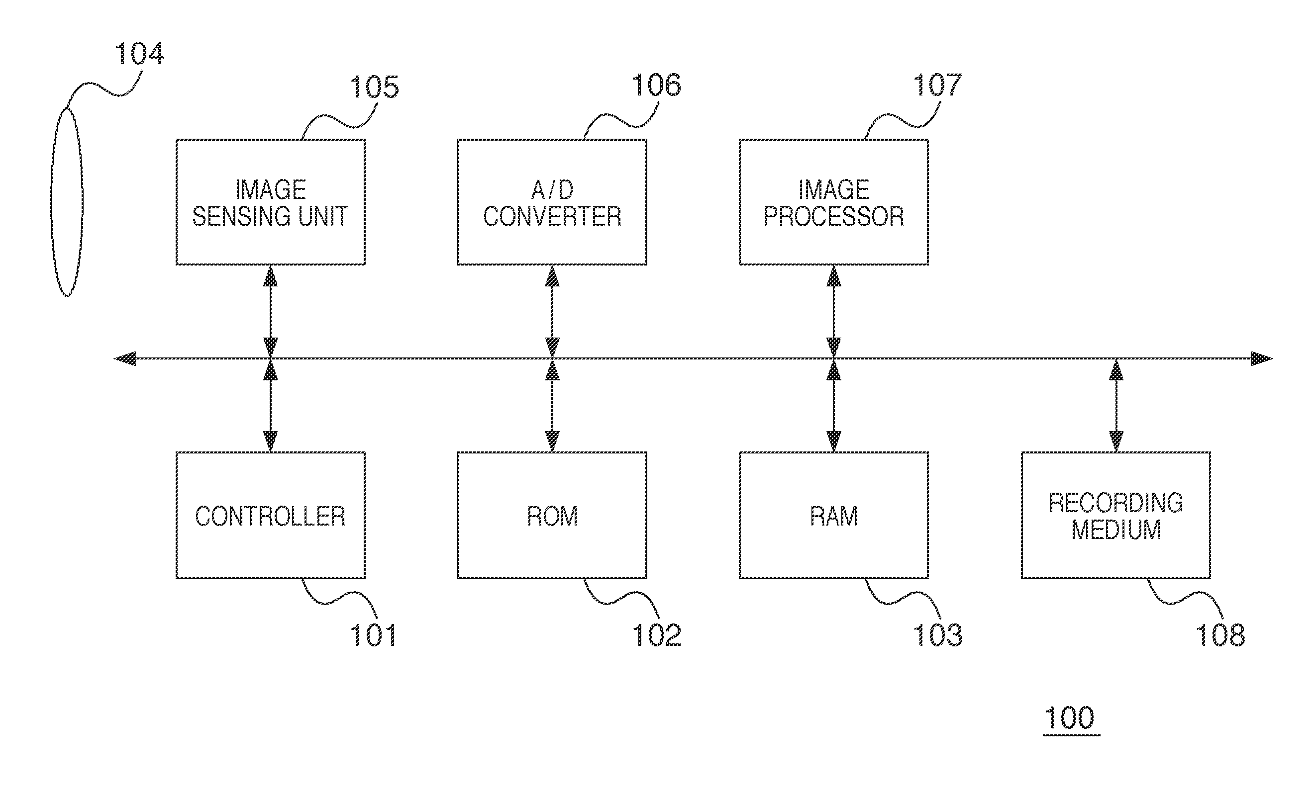
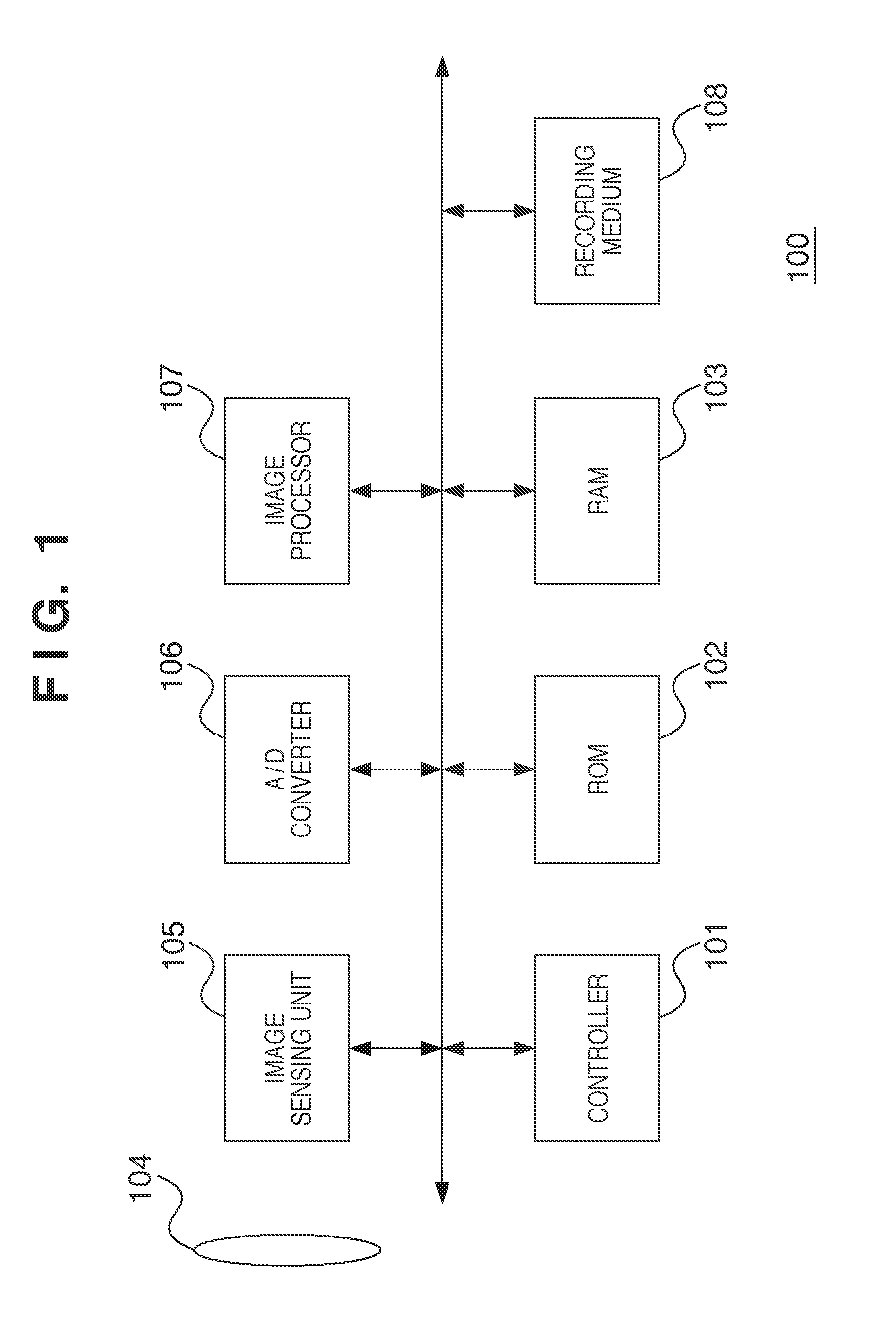
[0027]A preferred embodiment of the present invention will be described in detail hereinafter with reference to the accompanying drawings. Note that, in the embodiment described below, an example will be described in which the present invention is applied to a digital camera as an example image processing device that can correct blur in the captured image of an object that is caused by the motion of the imaging device on a region-by-region basis, where the image is divided into a plurality of regions. However, the present invention is applicable to any devices in which, when there are an input reference image and a input target image to be corrected, an offset (blur) of the target image from the reference image that is caused by the motion of an imaging device that captures the images is corrected on a region-by-region basis, where the target image is divided into a plurality of regions. As used herein, the term “local region” in the target image refers to on...

second embodiment

[0105](Second Embodiment)

[0106]In the first embodiment and variation described above, a technique of adjusting affine coefficients for each region in a target image by calculating a correction amount difference for only a local region or regions has been described. In this embodiment, a technique of correcting blur in an object image in a local region and regions neighboring the local region by calculating a correction amount difference of each of regions used for calculation of affine coefficients for the local region, using affine coefficients for the region and regions adjacent thereto.

[0107]As shown in FIG. 5, in this embodiment, the correction amount difference calculator 205 calculates correction amount differences of the points of interest U0, U1, U2, and U3 for the regions 38, 39, 46, and 47 used for calculation of affine coefficients for the local region 47 (i.e., one point of interest for each region). Specifically, for each point of interest, there is the following corres...


PUM


Abstract

An image processing device calculates a coordinate transformation coefficient for each of a plurality of regions, and, for at least one point of interest in a local region, calculates a correction amount that is used when blur in a target image is corrected using a coordinate transformation coefficient for the local region and a correction amount that is used when the blur in the target image is corrected using a coordinate transformation coefficient for a region neighboring the local region. In this case, if the correction amount difference does not fall within a predetermined limit value, a coordinate transformation coefficient is newly obtained for each of the plurality of regions including the local region so that the correction amount difference falls within the predetermined limit value, and the target image is corrected for each region using the newly obtained coordinate transformation coefficient.

Description

BACKGROUND OF THE INVENTION[0001]1. Field of the Invention[0002]The present invention relates to techniques for correcting blur in the image of an object that is caused by the motion of an imaging device.[0003]2. Description of the Related Art[0004]At present, imaging devices, such as digital cameras and the like, are often equipped with various functions for compensating for camera shake (i.e., image stabilization functions) in order to prevent the image of an object from being blurred by the motion of the image device due to, for example, camera shake caused by the user during shooting. There are basically two techniques of image stabilization, optical image stabilization and electrical image stabilization. In electrical image stabilization, a plurality of images captured are used to correct blur in the object image by image processing. Japanese Patent No. 4178481 discloses a technique of correcting blur in the object image by calculating a motion vector by feature pattern matchin...

Claims


Application Information

Patent Timeline
Patent Type & Authority Patents(United States)
IPC IPC(8): H04N5/228G06K9/40H04N23/40
CPCH04N5/23267H04N5/3572H04N23/60H04N23/683
Inventor MATSUOKA, MASAAKI
Owner CANON KK
Features
  • R&D
  • Intellectual Property
  • Life Sciences
  • Materials
  • Tech Scout
  • Unparalleled Data Quality
  • Higher Quality Content
  • 60% Fewer Hallucinations
Learn More