Timepiece

a timepiece and timepiece technology, applied in the field of timepieces, can solve the problems of affecting the operation of the piece, and the lower case still remains at least partially hidden,

Inactive Publication Date: 2013-07-02
COMPLITIME SA
View PDF12 Cites 15 Cited by
  • Summary
  • Abstract
  • Description
  • Claims
  • Application Information

AI Technical Summary

Problems solved by technology

The drawback of such a construction is that the lower case still remains at least partially hidden by the upper case.
More particularly, the elements of this control device are arranged in the space between the two cases, in which space dust can become lodged, which can harm the operation of the piece.
This means that outside the two service positions, i.e. when the case is open and is not superimposed on the second case, the lever no longer cooperates with the movement and the transmission of the information from the movement to the additional module is no longer ensured.
Moreover, the transmission of information at a frequency greater than once a day could lead to serious lags, detrimental to the precision of the additional mechanism.

Method used


Image

  • Timepiece
  • Timepiece
  • Timepiece

Examples


Embodiment Construction

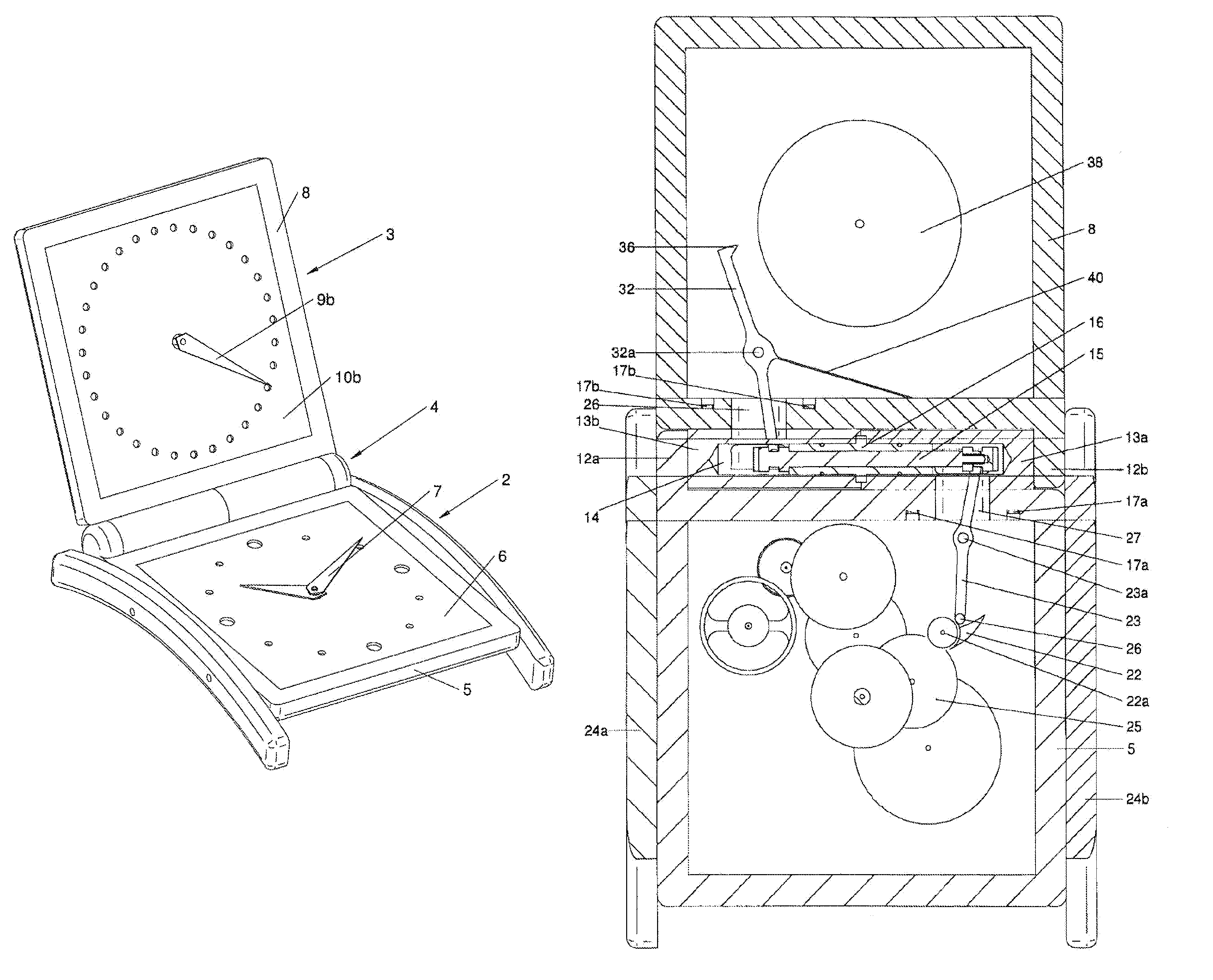
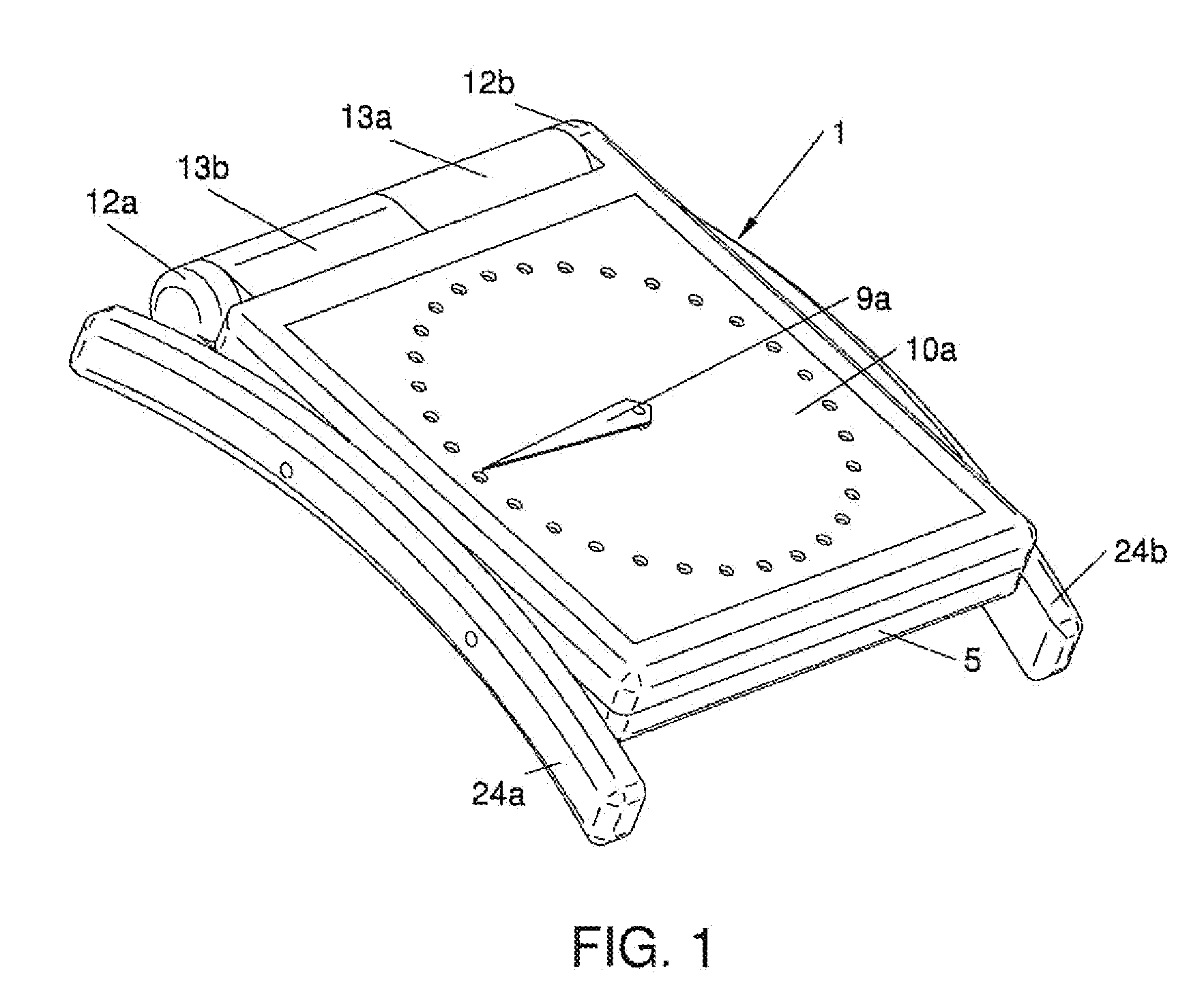
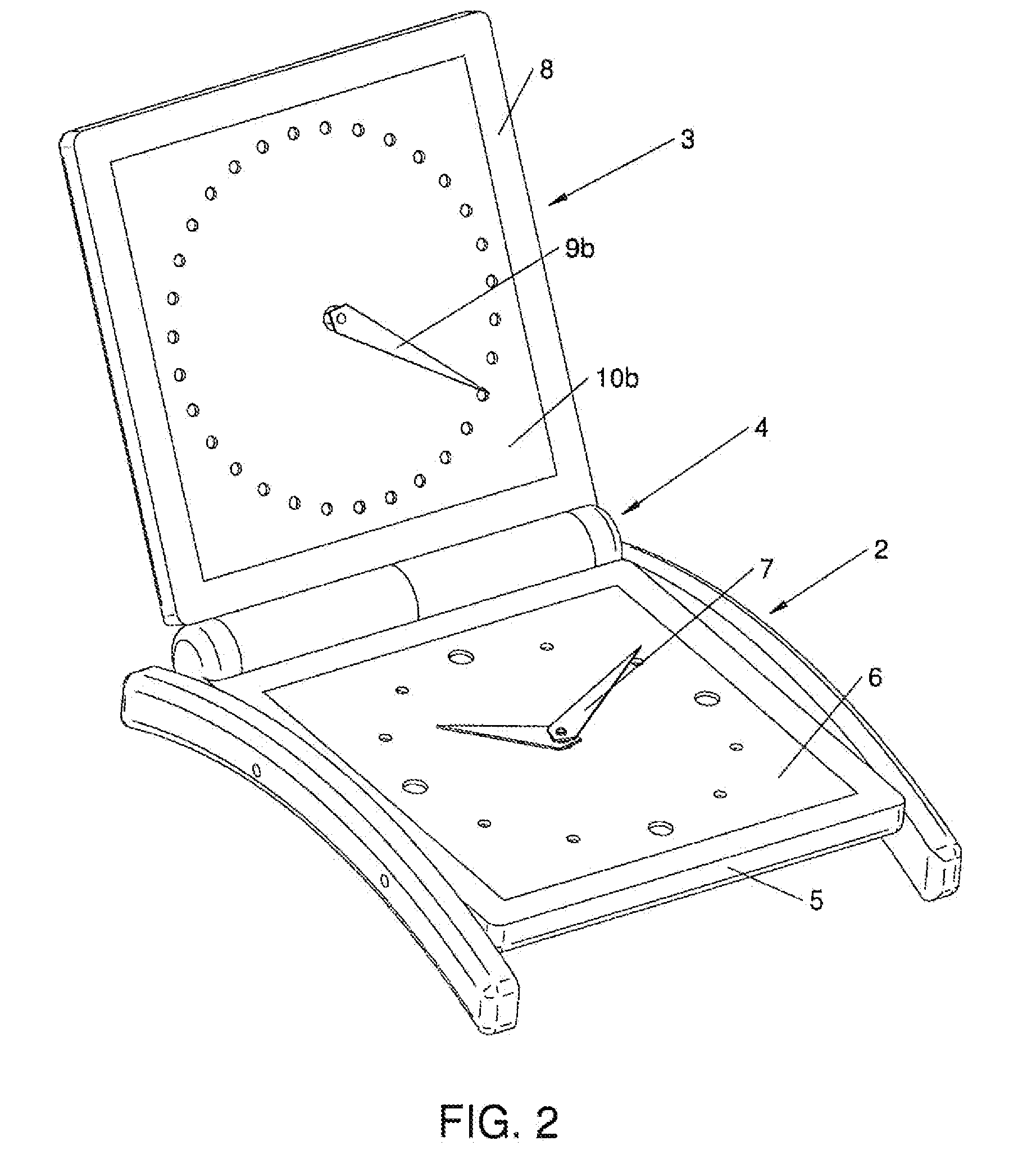
[0022]FIGS. 1 and 2 show a timepiece 1 comprising two cases 2 and 3 hinged relative to each other using a hinge 4. The first case 2 has, traditionally, a middle 5 closed by a glass, and contains a first part of a traditional mechanical clockwork movement, having a dial 6 and a hand 7 making it possible to display the hour and the minute. The first case 2 defines a first reference plane.

[0023]The second case 3 comprises a middle 8 closed on each side by a glass, and contains a second part of the movement, i.e. a mechanical date module, with two faces, comprising, on either side of the second case 3, an upper hand 9a and dial 10a and a lower hand 9b and dial 10b for displaying the date. Obviously the first and second parts can contain components having other functions. The second case 3 defines a second reference plane.

[0024]Each case 2, 3 respectively has a tab 12a, 12b, protruding on the edge corresponding to its back end, the two tabs 12a, 12b being arranged at the opposite ends of...


PUM


Abstract

A timepiece having a mechanical clock movement and separate first and second cases (2, 3), the movement including first and second portions housed in the first and second cases (2, 3), respectively, the cases (2, 3) being mutually connected in a rotatably hinged manner via a hinge (4) defining a pivot axis so as to be capable of forming a variable angle between the cases, the part further including a controller arranged to transmit information from one portion of the movement to the other. The controller includes at least one rod (15) slidably mounted in the hinge along an axis substantially parallel to the pivot axis and engaging with the first and second portions of the clock movement for transmitting information from one portion of the movement to the other, by a linear, alternating movement, regardless of the relative position of the two cases (2, 3).

Description

TECHNICAL FIELD[0001]The present invention relates to a timepiece comprising a mechanical clockwork movement, first and second distinct cases, said movement including first and second parts respectively housed in first and second cases, said cases being connected to each other hinged in rotation via a hinge defining a pivot axis so as to be able to form a variable angle between them, said piece also including a control device arranged to transmit information from one to the other of the parts of the movement. Mechanics here refers to a movement including mobile parts, animated by a spring or an electric motor.BACKGROUND OF THE INVENTION[0002]A timepiece of this type is for example described in patent application EP 1 513 031. In this example, the two cases pivot relative to each other around a pivot axis substantially perpendicular to the plane of the cases, so that the two cases slide one on the other when they are moved. In this way, the upper case is pivoted relative to the lower...

Claims


Application Information

Patent Timeline
Patent Type & Authority Patents(United States)
IPC IPC(8): G04B19/02
CPCG04B19/025G04B37/0016G04B37/0427
Inventor GREUBEL, ROBERTFORSEY, STEPHEN
Owner COMPLITIME SA
Why Eureka
Try Eureka