Electric function module assembly

a technology of function module and electric switch box, which is applied in the direction of identification means, coupling device connections, instruments, etc., can solve the problem of not revealing an electric switch box comprising a pair of electrical contacts, and achieve optimal energy and monetary conservation

Inactive Publication Date: 2013-09-10
CUTLER PAUL
View PDF16 Cites 6 Cited by
  • Summary
  • Abstract
  • Description
  • Claims
  • Application Information

AI Technical Summary

Benefits of technology

[0028]The use of the present invention allows consumers to exercise and enjoy optimum energy and monetary conservation.

Problems solved by technology

However, the prior art does not disclose an electric switch box comprising a pair of electrical contacts adapted for slidable connective engagement with a respective pair of electrical contacts of a switch cover.

Method used


Image

  • Electric function module assembly
  • Electric function module assembly
  • Electric function module assembly

Examples


Embodiment Construction

Detailed Description of the Figures

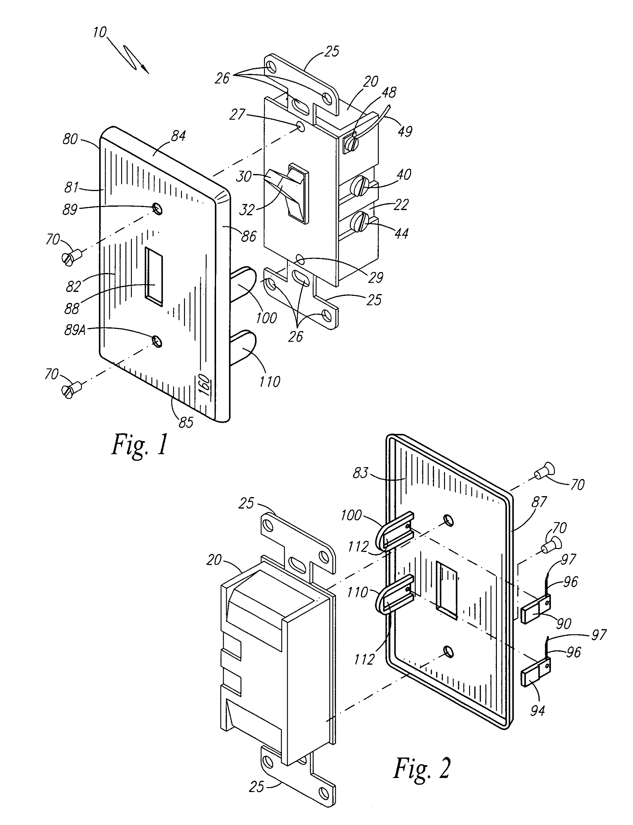
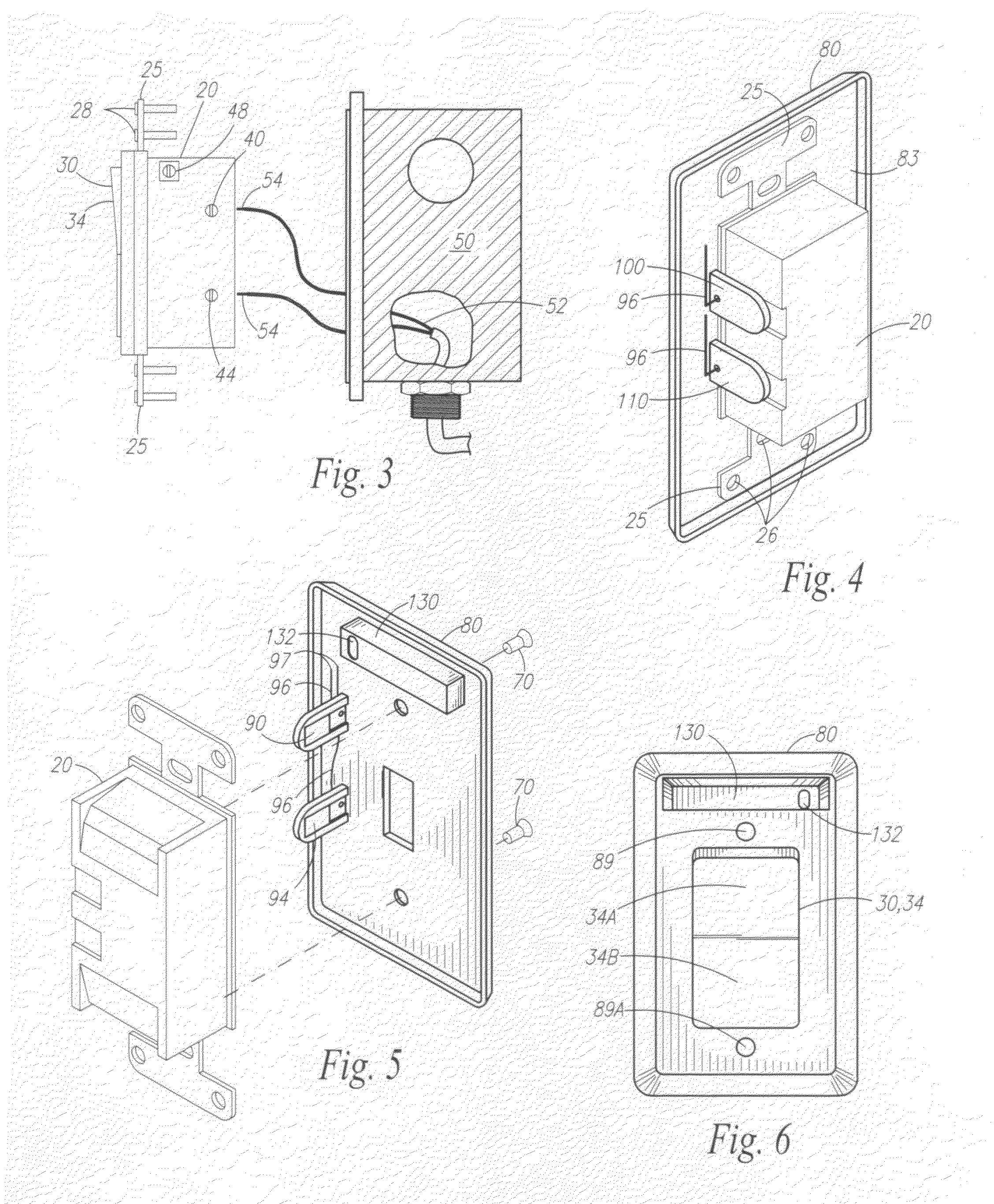
[0050]With reference to FIGS. 1-4, an electric function module assembly 10 is disclosed, according to one embodiment of the present invention. The electric function module assembly, hereinafter “assembly 10”, comprises an electric switch box 20 having a mechanical movement means 30 for actuation of the electric switch box 20. The mechanical movement means 30 may be a toggle bat 32 or a rocker arm 34 for actuating the electric switch box 20. The assembly 10 may be permanently affixed to a standard electrical junction box 50 providing electric power wiring 52. The electrical power wiring 52 has exposed ends 54 attached to the electric switch box 20 by conventional means.

[0051]The electric switch box 20 comprises a first electrical contact 40 and a second electrical contact 44, the electrical contacts 40 and 44 having an electrical load wired in series therewith. The electric switch box 20 includes a third electrical contact 48 to which a ground wire ...


PUM


Abstract

An electric function module assembly is disclosed. The assembly includes an electric switch box having a pair of electrical contacts adapted for slidable connective engagement with a respective pair of electrical contacts of a switch cover. The contacts of the switch cover are electrically connected to a function indicator to operate the function indicator.

Description

RELATED APPLICATIONS[0001]There are no previously filed, nor currently any co-pending applications, anywhere in the world.BACKGROUND OF THE INVENTION[0002]1. Field of the Invention[0003]This application discloses and claims embodiments related generally to electrical switches, and more particularly, to an electric function module assembly.[0004]2. Description of the Related Art[0005]The prior art teaches numerous wall plate switch assemblies, electrical connection boxes for electrical modules, and light switch covers or plates for mounting over existing wall switches. However, the prior art does not disclose an electric switch box comprising a pair of electrical contacts adapted for slidable connective engagement with a respective pair of electrical contacts of a switch cover.[0006]Accordingly, a need has arisen for an electric function module assembly comprising an electric switch box having a pair of electrical contacts adapted for slidable connective engagement with a respective ...

Claims


Application Information

Patent Timeline
Patent Type & Authority Patents(United States)
IPC IPC(8): G08B5/22
CPCH01H9/181H01H23/025H02G3/14
Inventor CUTLER, PAUL
Owner CUTLER PAUL
Why Eureka
Try Eureka