Fast action shock invariant magnetic actuator for firearms

a fast action, magnetic actuator technology, applied in the field of firearms, can solve problems such as insufficient force generation, and achieve the effects of small size, simple switching logic, and fast actuation

Active Publication Date: 2020-11-05
STURM RUGER & CO INC
View PDF0 Cites 5 Cited by
  • Summary
  • Abstract
  • Description
  • Claims
  • Application Information

AI Technical Summary

Benefits of technology

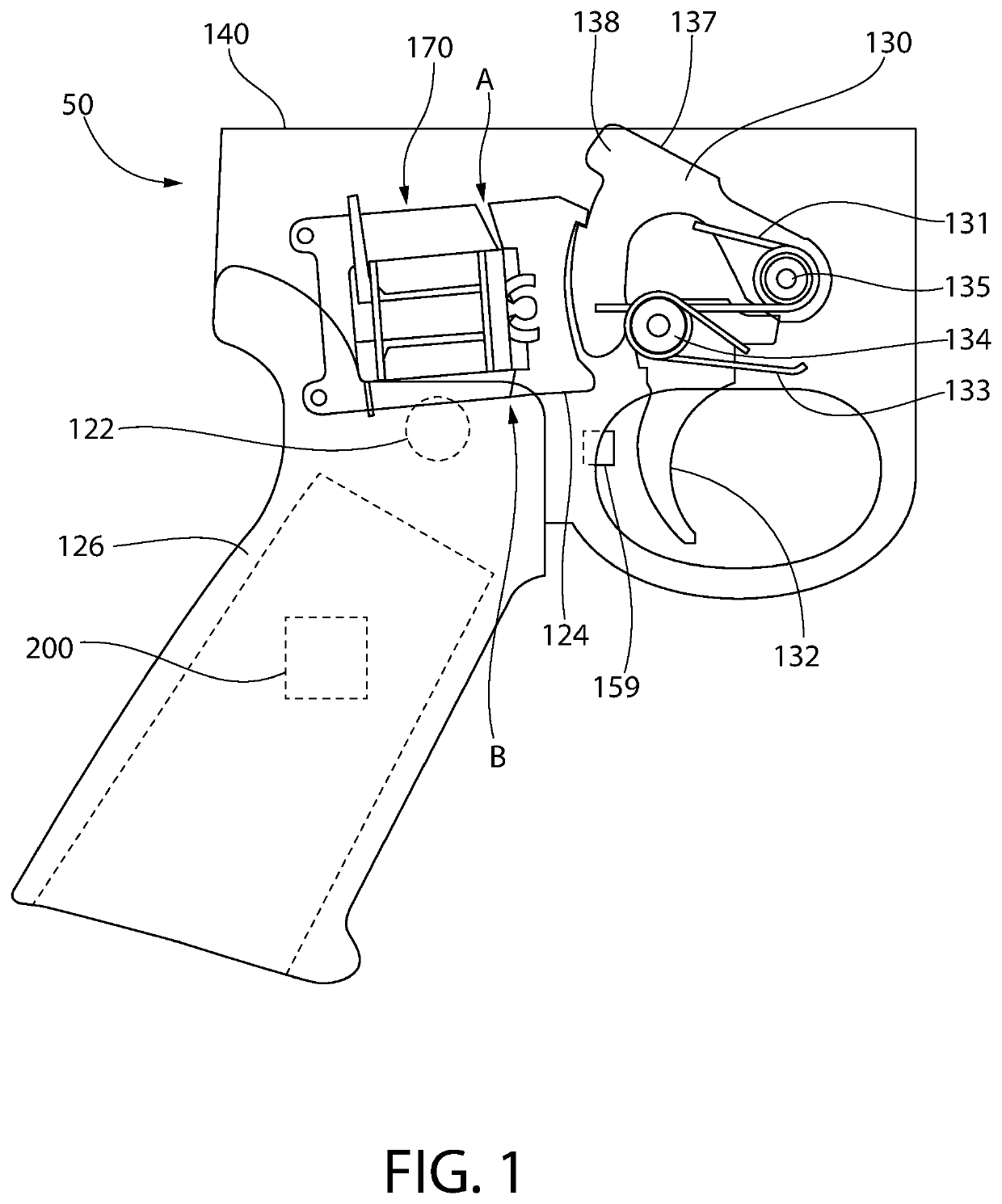
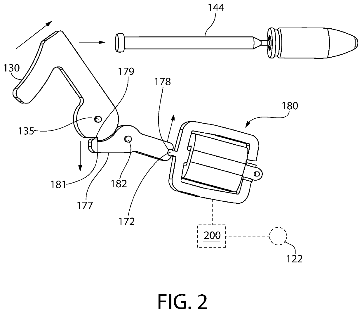
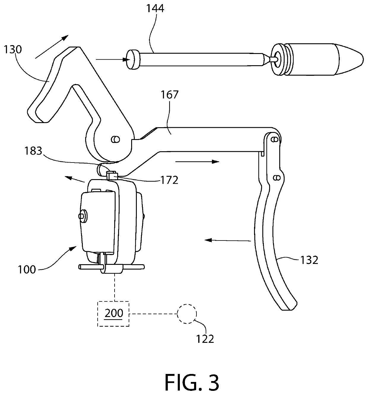
[0006]According to an embodiment of the present invention, an electromagnetic actuator suitable for a firearm is disclosed that provides the novel combination of very fast actuation, shock invariant design, small size, and which can be controlled using a small low voltage battery power source and simple switching logic. In one embodiment, very fast snap-like action is attained by balancing the forces of two opposing permanent magnets around a central yoke and rotating member to create three circulating magnetic flux circuits. A central electromagnet coil in the center of the yoke amplifies the magnetic flux of one side of the rotating member or the other depending on the actuation polarity. As the rotating member begins to change state or position, an air gap opens on the opposing side (previously closed) of the rotating member and the combined change in reluctance in the three circulating magnetic flux circuits causes a rapid increase in the flux density on the closing side (previously open) of the rotating member and a rapidly decreasing force on the opening side resulting in a very fast snap action closure of the rotating member. This creates two possible actuation positions of the rotating member which can interact and be interfaced with the firing mechanism of a firearm in either a firing mechanism component release application to discharge the firearm, or alternatively a firing mechanism blocking / enablement application each of which is further describe herein.

Problems solved by technology

The disclosed actuator design may have a center of rotation of the rotating member sufficiently close to the center of mass of the rotating member such that random linear acceleration forces from any direction will not generate sufficient force to overcome the static holding force of the permanent magnets on the rotating member.

Method used


Image

  • Fast action shock invariant magnetic actuator for firearms
  • Fast action shock invariant magnetic actuator for firearms
  • Fast action shock invariant magnetic actuator for firearms

Examples


Embodiment Construction

[0086]The features and benefits of the invention are illustrated and described herein by reference to example (“exemplary”) embodiments. This description of exemplary embodiments is intended to be read in connection with the accompanying drawings, which are to be considered part of the entire written description. In the description of embodiments disclosed herein, any reference to direction or orientation is merely intended for convenience of description and is not intended in any way to limit the scope of the present invention. Relative terms such as “lower,”“upper,”“horizontal,”“vertical,”, “above,”“below,”“up,”“down,”“top” and “bottom” as well as derivative thereof (e.g., “horizontally,”“downwardly,”“upwardly,” etc.) should be construed to refer to the orientation as then described or as shown in the drawing under discussion. These relative terms are for convenience of description only and do not require that the apparatus be constructed or operated in a particular orientation. T...


PUM


Abstract

An electromagnetic actuator includes characteristics of very fast actuation, shock invariant design, and compact size. The actuator may be controlled via a small low voltage power source such as a battery and simple switching logic. Such characteristics are ideally suited for incorporating the actuator into the firing mechanism of a firearm, which are subjected to drop tests to confirm the firearm will not discharge in the absence of trigger pull. Very fast snap-like action is attained by balancing the magnetic forces of two opposing permanent magnets around a stationary yoke and rotating member to create three circulating magnetic flux circuits. A central electromagnet coil amplifies the magnetic flux of one side of the rotating member or the other depending on the power source actuation polarity, thereby creating two possible snap-like actuation positions. The actuator is usable in firing mechanism release or enabling/disabling applications, and interfacing with other type mechanical linkages.

Description

CROSS-REFERENCE TO RELATED APPLICATIONS[0001]The present application is a continuation-in-part of U.S. application Ser. No. 16 / 504,594 filed Jul. 8, 2019, which is a continuation of U.S. application Ser. No. 16 / 265,077 filed Feb. 1, 2019 (now U.S. Pat. No. 10,378,848), which is a continuation of U.S. application Ser. No. 15 / 908,874 filed Mar. 1, 2018 (now U.S. Pat. No. 10,240,881), which claims the benefit of priority to U.S. Provisional Application No. 62 / 468,679 filed Mar. 8, 2017. The foregoing applications are incorporated herein by reference in their entireties.BACKGROUND OF THE DISCLOSURE[0002]The invention pertains generally to firearms, and more specifically to battery powered fast-action actuators for use in critical high shock and acceleration exposure environments such as in firearms.[0003]Electromagnetic actuators are typically not used in small portable applications where a reliable fast action, high force, and large displacement is needed, but instead small size, low b...

Claims


Application Information

Patent Timeline
Patent Type & Authority Applications(United States)
IPC IPC(8): F41A19/59F41A19/16
CPCF41A19/16F41A19/59
Inventor GALIE, LOUIS M.GILLIOM, ROBKLEBES, JOHNFRENCH, JOHN M.HAMILTON, GARY
Owner STURM RUGER & CO INC
Why Eureka
Try Eureka