Packages having bubble-shaped closures

a packaging and bubble technology, applied in the field of flexible packaging, can solve the problems of failure of a true closure, breach of interlocking components, and the manufacturing of additional and often costly materials and/or devices into the packages, and achieve the effect of repeatable sealing performan

Active Publication Date: 2013-12-24
STEELE MARK
View PDF101 Cites 63 Cited by
  • Summary
  • Abstract
  • Description
  • Claims
  • Application Information

AI Technical Summary

Benefits of technology

[0013]For various embodiments, a pair of thin-walled, fluid-filled chambers, one each on opposing sides of a bag or package (e.g., flexible, rigid or semi-rigid) proximate the opening of the bag, span the width of a flexible bag and are arranged to contact each other to form a seal when the opening is closed. Because of the thin-walled design, the forces required to maintain a seal therebetween are well within the elastic limits of the chamber material for a repeatable sealing performance over the life of the package. The opening to the bag may be closed by conventional means used in the packaging industry, such as by zipper closures, press-to-close closures, hook and loop fabric fasteners, tin-tie closures, snaps or other techniques available to the artisan. The closure mechanism causes the opening to remain closed and the fluid-filled chambers to maintain contact with each other across the length of the opening. In this way, the closure mechanism may provide a primary closure and the contacting fluid-filled chambers may provide a secondary seal, which can provide a leak proof or air tight package or opening.

Problems solved by technology

These devices often require the manufacturing of additional and often costly materials and / or devices into the packages.
These press-to-close closure mechanisms are sometimes difficult to align when attempting to mate together, often causing a failure of a true closure.
Furthermore, when a packager is filling the package through the press-to-close closure mechanism, and when the consumer is pouring the contents out of the package, small pieces of the product can get caught in tracks of the mating interlocking members, causing a breach across the interlocking components and hampering any positive seal.
The compromise of the integrity of the seal between the mating locking components may also be caused by localized crushing (e.g., proximate side seal) of the interlocking members during manufacturing, shipping, handling, and use by the consumer.
First, it reduces the internal holding volume of the package since, in a closed position, side gussets of the package are forced to contact at an end proximate the access opening.
Second, a space or gap can remain when the zipper-type closure mechanism is in its closed position.
Although the zipper-type closures may be easier for some consumers to operate, and may have a more positive closure with respect to the press-to-close closure mechanism, they can be expensive and, like the press to close closure mechanisms, often do not create an ideal barrier after the package has been opened by the consumer for the first time.
However, the interlocking members of both the zipper and the press-to-close closure mechanisms may also allow for fluid leakage and they may undergo plastic deformation after repeated use that adversely affects the ability of the mechanism to seal fluids.
Moreover, the zipper and press-to-close mechanisms may not be suitable for a gas tight seal.
Accordingly, the contents of the package are susceptible to oxidation and other air-borne problems, such as the release of odors.

Method used


Image

  • Packages having bubble-shaped closures
  • Packages having bubble-shaped closures
  • Packages having bubble-shaped closures

Examples


Embodiment Construction

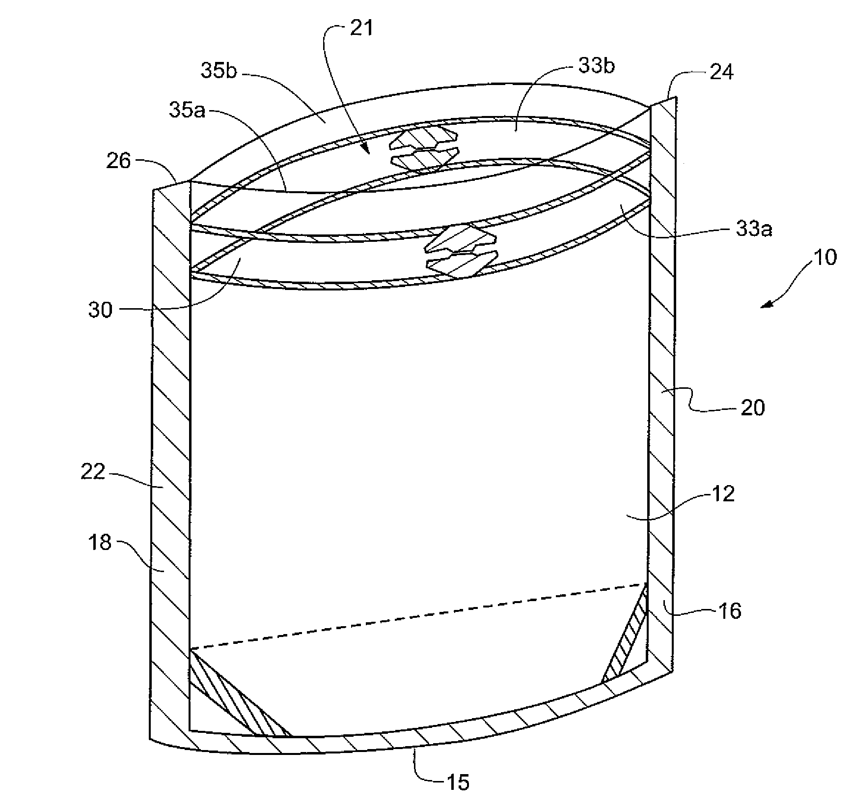
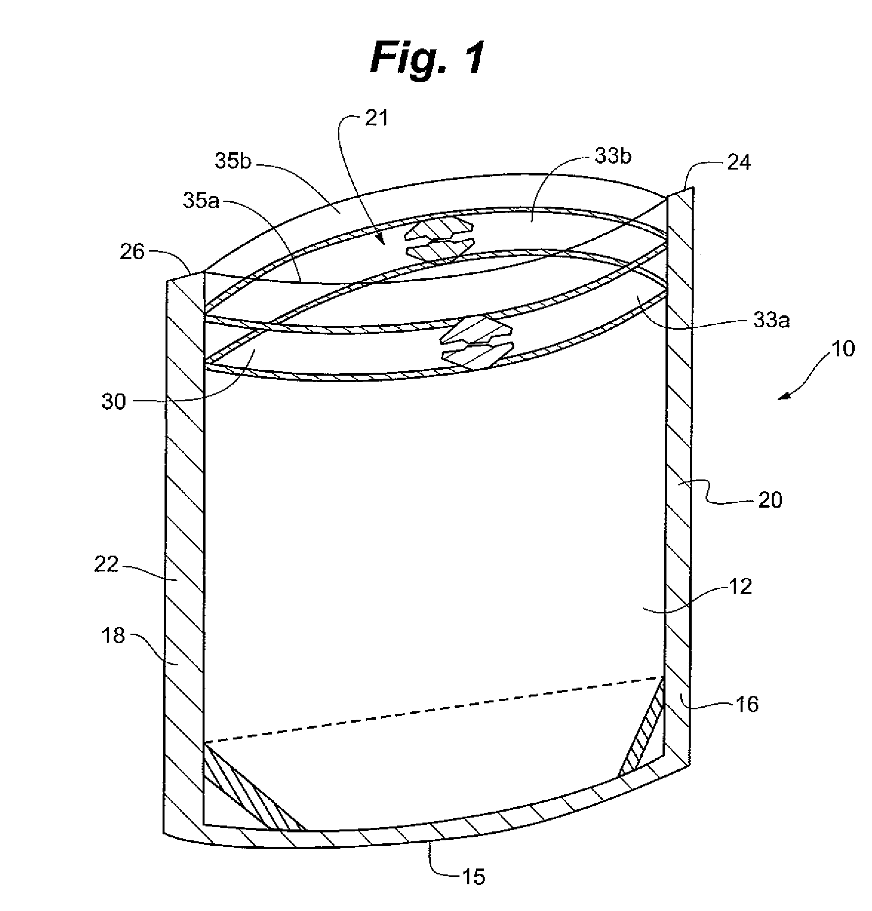
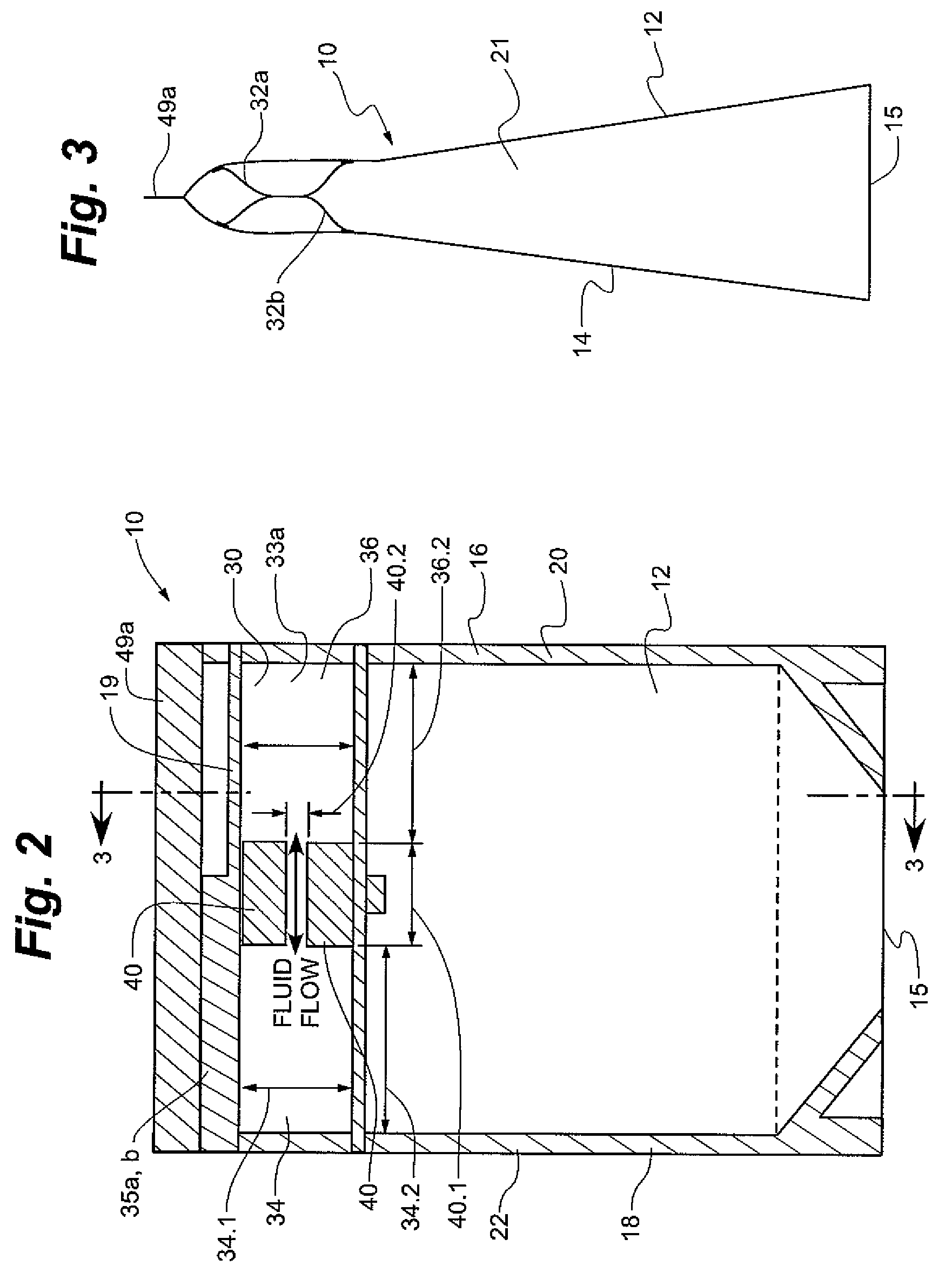
[0073]Referring generally to FIGS. 1-16, a flexible package 10 in accordance with the present invention is shown. Referring generally to FIGS. 1-3, the package 10 generally includes a front panel portion 12, a back panel portion 14. Further, a bottom panel portion 15, gusseted or non-gusseted, can be included, especially in those embodiments defining a stand up package. The joining and / or shaping of the panels 12, 14, 15, generally define an inner cavity 21 having an adjustable internal volumetric capacity. The inner cavity 21 is capable of storing, transporting and / or dispensing product or other objects and material therein. Side panel portions (not shown), gusseted or non-gusseted, may also be included. The panel portions 12-15 are often referred to as webs, films or layers.

[0074]The package panel portions 12-15 are generally constructed of a flexible sheet material such as polyethylene, polyester, metal foil, polypropylene, or polyethylenes laminated with other materials such as ...


PUM

PropertyMeasurementUnit
lengthaaaaaaaaaa
flexibleaaaaaaaaaa
areaaaaaaaaaaa

Abstract

A package having fluid-filled chambers that form a line of contact that seals the package. The package generally defines an interior cavity accessible through an opening. Opposing portions of the opening may include at least one fluid-filled chamber to seal the package. The chamber may be held in sealing contact with an opposing structure or with each other by fastening means that hold the opposing portions together. In another embodiment, opposing chambers themselves may interlock to maintain sealed contact. The package may include an auxiliary opening so that an end user can fill the package with articles of the user's choice. The auxiliary opening can be sealed at least over a portion of its length. In another embodiment, first and second compartments are isolated by the fluid-filled chamber seal, with the seal being selectively breachable to enable transfer of product from the first to the second compartment.

Description

RELATED APPLICATIONS[0001]This application is a continuation-in-part of U.S. patent application Ser. No. 11 / 737,866, filed Apr. 20, 2007, which is a continuation of U.S. patent application Ser. No. 11 / 268,674, filed Nov. 7, 2005, now U.S. Pat. No. 7,207,717, issued Apr. 24, 2007, which claims priority to U.S. Provisional Application Ser. No. 60 / 625,391, filed Nov. 5, 2004. This application also claims priority to U.S. Provisional Application Ser. No. 60 / 916,442, filed May 7, 2007, to U.S. Provisional Application Ser. No. 60 / 917,078, filed May 10, 2007, to U.S. Provisional Application Ser. No. 60 / 952,311, filed Jul. 27, 2007, and to U.S. Provisional Application Ser. No. 60 / 987,588, filed Nov. 13, 2007. The disclosures of the above referenced applications are hereby incorporated by reference herein in their entirety.FIELD OF THE INVENTION[0002]The present invention relates generally to flexible packaging and, more particularly, to packages, and methods for manufacturing and using pack...

Claims


Application Information

Patent Timeline
Patent Type & Authority Patents(United States)
IPC IPC(8): B65D33/16
CPCB31B19/84B31B23/00B65D33/01B65D33/16B31B2219/9058B31B2237/10B31B2237/40B31B2237/406B65D75/008B31B70/00B31B70/855B31B2155/00B31B2155/001B31B2155/0014B31B2160/10
Inventor STEELE, MARK
Owner STEELE MARK
Why Eureka
Try Eureka