Disk-based valve apparatus and method for the treatment of valve dysfunction

a valve apparatus and valve technology, applied in the field of valve implantation, can solve the problems of inability to achieve the effect of distal anchoring of the device, limited information on the efficacy of the procedure, and inability to achieve the effect of distal anchoring, facilitating the centering and stability of the valve apparatus,

Active Publication Date: 2014-05-20
CEPHEA VALVE TECH
View PDF508 Cites 342 Cited by
  • Summary
  • Abstract
  • Description
  • Claims
  • Application Information

AI Technical Summary

Benefits of technology

[0065]The disk-based valve apparatus comprising one or more disks allows the repositioning and retrieval of the implantable valve while working on a dysfunctional valve structure.
[0066]The present invention comprises a novel and safer mechanism of deployment using a self-positioning, self-centering, and self-anchoring method. The valve apparatus, comprising one or more disks, dependently or independently interacting with each other, is maintained in place by the anchoring of the proximal and / or distal disks. Such mechanism allows the self-positioning, self-centering, ad self-anchoring of the valve, thus, maintaining the overall inflow plane of native valvular apparatus.
[0067]Furthermore, the valve apparatus comprises a double structure having a valve-housing component. The valve-housing component allows the device to be uniquely shaped and to distinguish from all other disk-based valve apparatus. Additionally, the particular shape and configuration of the distal disk ease the distal anchoring of the device. On the other end, the proximal disk facilitates the centering and stability of the valve apparatus.

Problems solved by technology

Although these valves may incorporate desirable features, little information is currently available on their efficacy, procedural outcomes, and durability.
Percutaneous Energy-Mediated Cinching Approach: Heat energy is applied to the MA, causing scarring and shrinkage of the MA.
The challenges are formidable: the MA has an asymmetrical saddle shape, and different anchoring designs might be necessary for different MR etiologies.
LV out flow obstruction might occur due to retained native valve tissue.
Furthermore paravalvular leaks might also pose a problem.
As described above, the mitral valve apparatus has multiple components and displays a complex anatomical shape and structure thus limiting the number of any prevailing mitral valve repair solutions.
The mitral valve technologies currently under development are actually composed of rigid valve structures, which usually distort the mitral valve plane and apparatus with unknown clinical results.
Although commonly used for treating calcified aortic stenosis, these structures are not proper fit for non-symmetrical shapes such as the mitral valve.
Often resulting in para-valvular leaks following device implantation, symmetrical balloon geometries are not ideal.
Although, self-expanding structures are an improvement over balloon expandable ones, a one-piece structure in a symmetrical upper and lower part of mitral valve apparatus is not ideal either.
Different radial pressures might be needed against surrounding tissue potentially causing deleterious effects such as conduction system disturbances or tissue disruption.

Method used


Image

  • Disk-based valve apparatus and method for the treatment of valve dysfunction
  • Disk-based valve apparatus and method for the treatment of valve dysfunction
  • Disk-based valve apparatus and method for the treatment of valve dysfunction

Examples


second embodiment

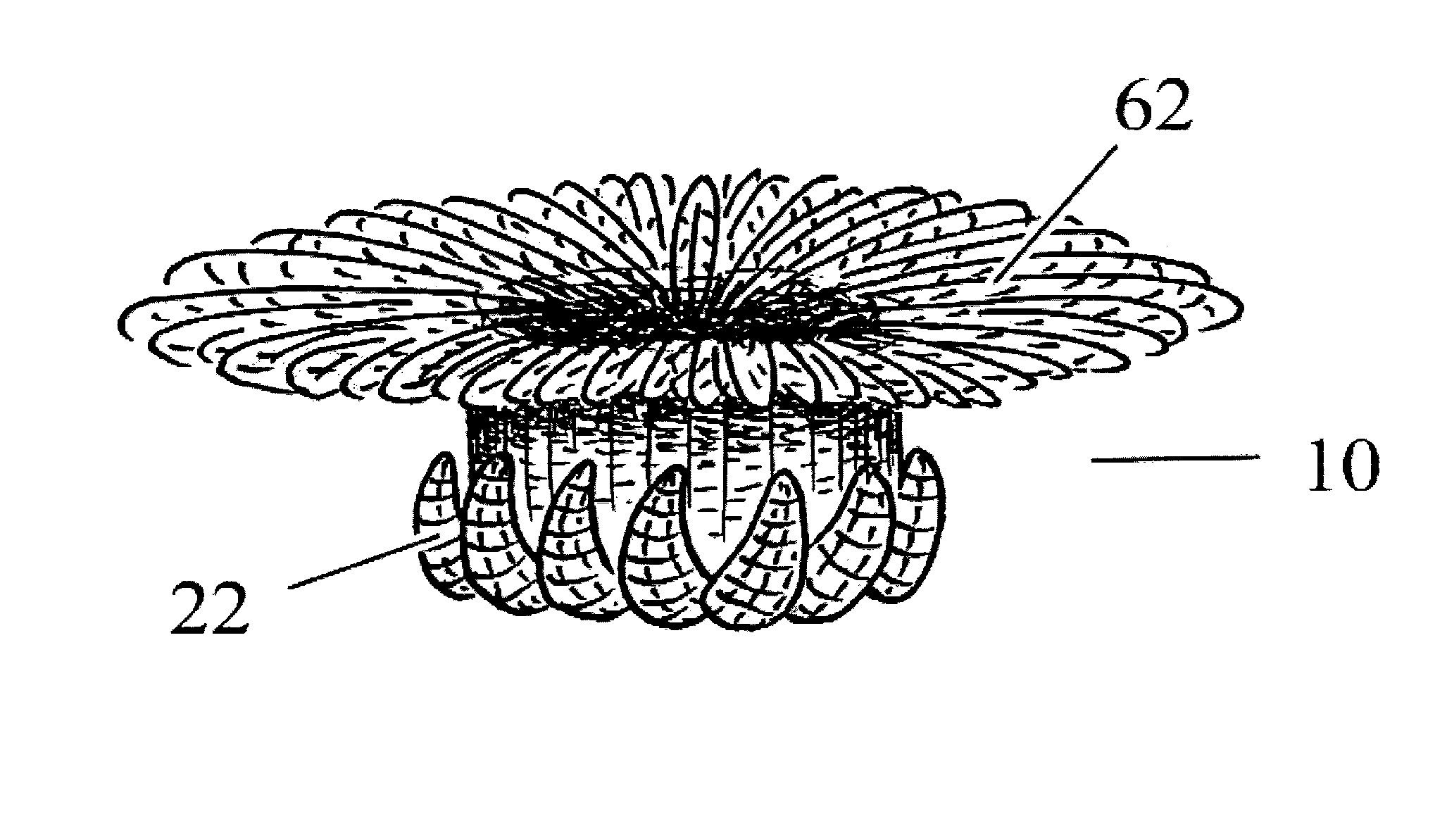
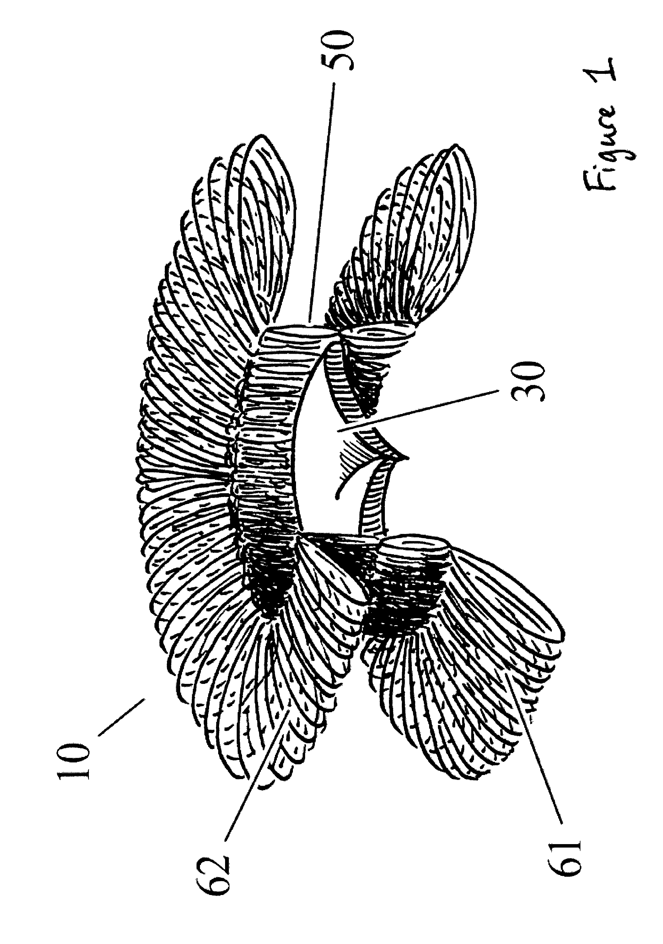
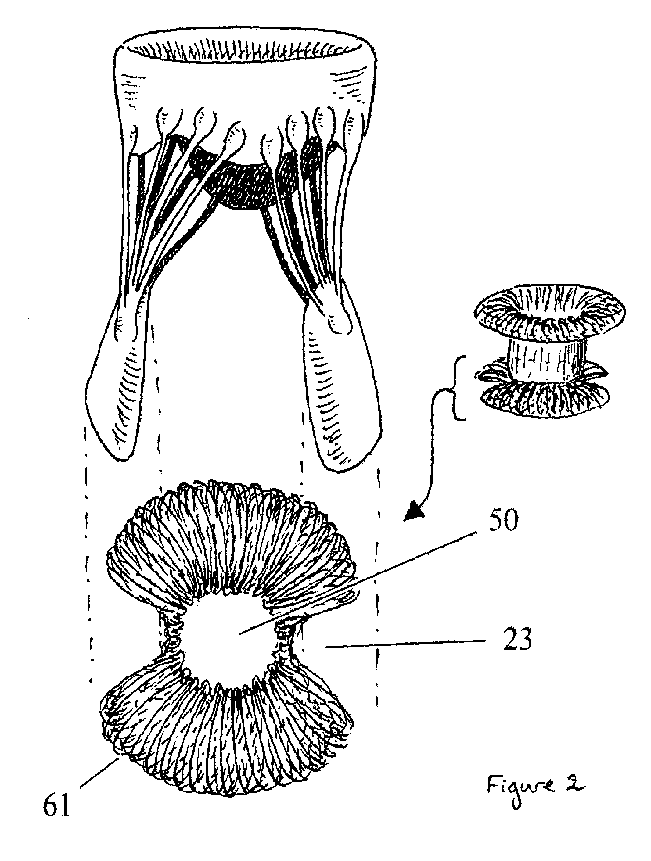
[0109]In a further second embodiment, which is similar to the embodiment described above, the valve apparatus 10 comprises a single distal anchoring disk 61. When the insertion of the apparatus 10 is completed within the patient's dysfunctional valve, a distal disk 61 is released. At this point, the distal disk 61 is partially deformed and the valve-component housing 50 is positioned at the level of the dysfunctional valve plane. Then, the proximal segment of the apparatus 10 is fully released to complete the positioning of the valve apparatus 10.

[0110]In a further third embodiment, which is based on the further second embodiment, the valve apparatus 10 comprises a single distal anchoring disk 61 and a smaller and shorter proximal disk 62. When the insertion of the valve apparatus 10 is completed within the patient's dysfunctional valve, the distal disk 61 is released. At this point, the distal disk 61 is partially deformed and the valve-component housing 50 is positioned at the lev...

fourth embodiment

[0111]In a further fourth embodiment, as shown in FIG. 6, a valve apparatus 10 comprises a plurality of independent units, which may be hollowed, a valve component 30 generally located in the central portion 50 and at least two separate anchoring systems 20 or disks 60. When the insertion of the valve apparatus 10 is completed, the distal disks 61 are released. Even if not required, each distal disk 61 may comprise one or more additional anchoring structures allowing the sub-valvular to be anchored and positioned in regards to the distal disk 61. Upon deformation of the distal disk 61, the apparatus 10 is pulled back into the plane of the dysfunctional valve in order to position the valve component 30 located in the valve-component housing 50. The valve apparatus 10 is positioned into an expandable structure, such as a balloon. The expandable structure may be deployed following initial positioning of the valve apparatus 10. Once positioned, a second disk 62 is released in order to s...

fifth embodiment

[0112]In a further fifth embodiment, as shown in FIG. 7, a valve apparatus 10 comprises a plurality of wires 63 distributed in a way to form one or more disks 60, either distal 61 or proximal 62, and a valve component 30 generally located in the central portion 50. Each wire 63 may comprise an anchoring mechanism such as a hook or needle. When the insertion of the valve apparatus 10 is completed, the distal disk 61 is released. Upon deformation of the distal disk 61, the apparatus 10 is pulled back into the plane of the dysfunctional valve in order to position the valve component 30 located in the valve-component housing 50. Once positioned, a second disk 62 is released in order to secure the entire apparatus 10 in place. The configuration of this embodiment may be changed or adapted according to the route of insertion, such as anterograde versus retrograde or percutaneous versus trans-apical versus trans-atrial.


PUM


Abstract

The present invention comprises a novel and safer mechanism of deployment using a self-positioning, self-centering, and self-anchoring method. To embody the present invention, a disk-based valve apparatus allowing the repositioning and retrieval of the implantable valve while working on a dysfunctional valve structure is disclosed. The disk-based valve apparatus may comprise one or more disks, either proximal or distal, a valve-housing component and a valve component. The one or more disks may be either proximal or distal, may be either connected to each other or disconnected from each other and may either be symmetrical or have different shapes and dimensions. The disk-based valve apparatus may be self anchoring, such as anchored by pressure from the one or more disk, or may be anchored using any anchoring.

Description

CROSS-REFERENCE TO RELATED APPLICATIONS[0001]This application is a continuation of PCT / IB2012 / 000563, filed Mar. 21, 2012, which application claims the benefit of priority of commonly assigned U.S. patent application Ser. No. 61 / 454,703, filed Mar. 21, 2011, and entitled “Multiple Disk Self-Positioning Apparatus and Method for the Treatment of Valve Dysfunction”.FIELD OF THE INVENTION[0002]The present invention generally relates to valve implantation and more specifically to the percutaneous replacement of dysfunctional valves.BACKGROUND OF THE INVENTIONa) Transcatheter Aortic Valve Implantation (TA VI)[0003]In addition to the initial commercially approved devices for transcatheter aortic valve implantation (TAVI) such as the Edwards-Sapien™ THV balloon expandable bovine bioprosthesis (Edwards Lifesciences INC, Irvine, Calif., USA) and the Core Valve ReValving® System (Medtronic Inc., Minneapolis, Minn., USA), nitinol porcine self-expanding bioprosthesis, a number of newer devices h...

Claims


Application Information

Patent Timeline
Patent Type & Authority Patents(United States)
IPC IPC(8): A61F2/24
CPCA61F2230/0078A61F2230/005A61F2/2409A61F2/2445A61F2/2418A61F2230/0058A61F2230/0065A61F2220/0008A61F2220/0075A61F2250/0039
Inventor MONTORFANO, MATTEOCHIEFFO, ALAIDEGRANADA, JUAN F.
Owner CEPHEA VALVE TECH
Why Eureka
Try Eureka