
Dry vacuum pump having multiple lubricant reservoirs
a vacuum pump and reservoir technology, applied in the direction of fluid removal, rotary piston engines, combustion processes, etc., can solve the problems of increased operating temperatures, brittle frictional ring seals, and insufficient safety measures, so as to increase the service life of the ring seal
- Summary
- Abstract
- Description
- Claims
- Application Information
AI Technical Summary
Benefits of technology
Problems solved by technology
Method used
Image

Examples
Embodiment Construction
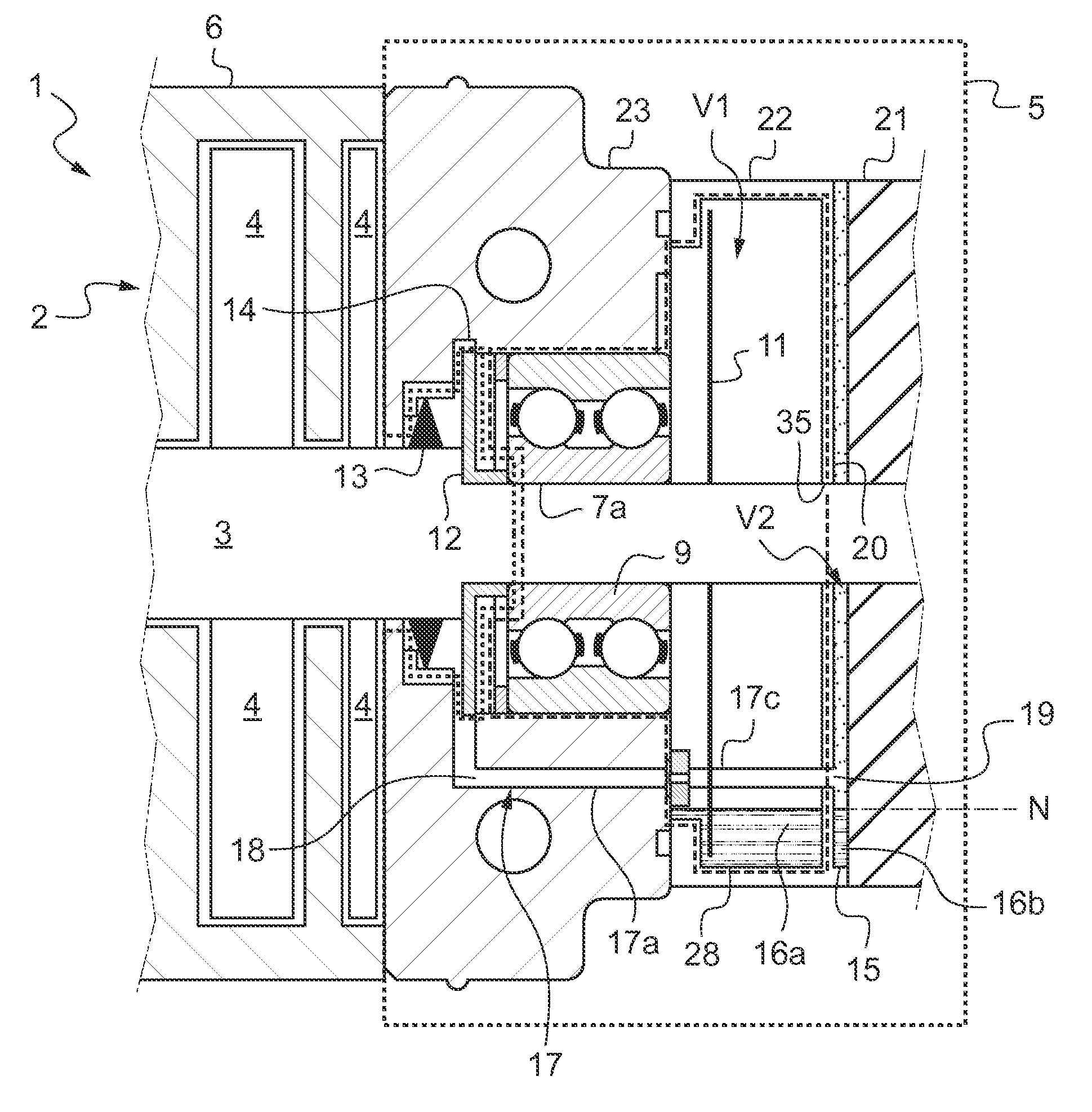
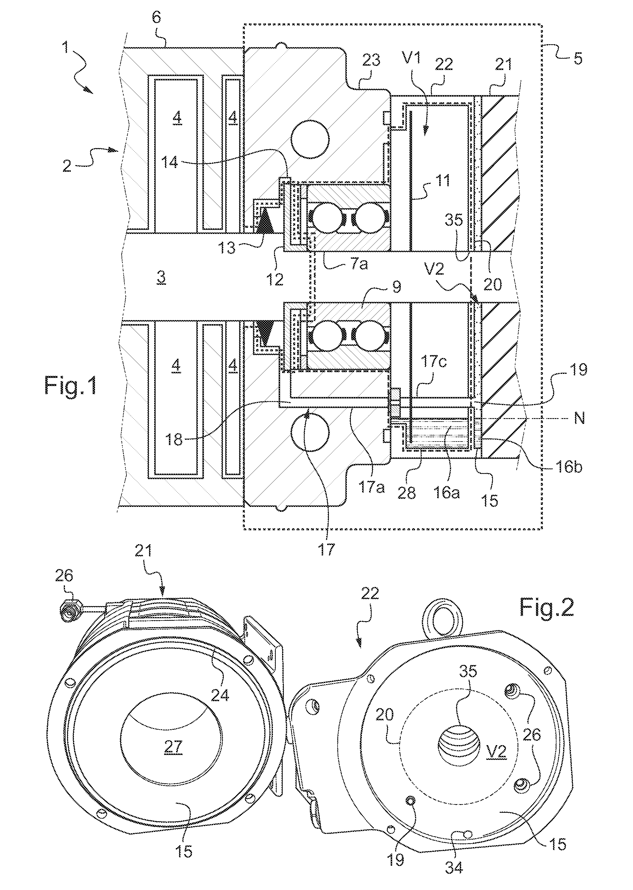
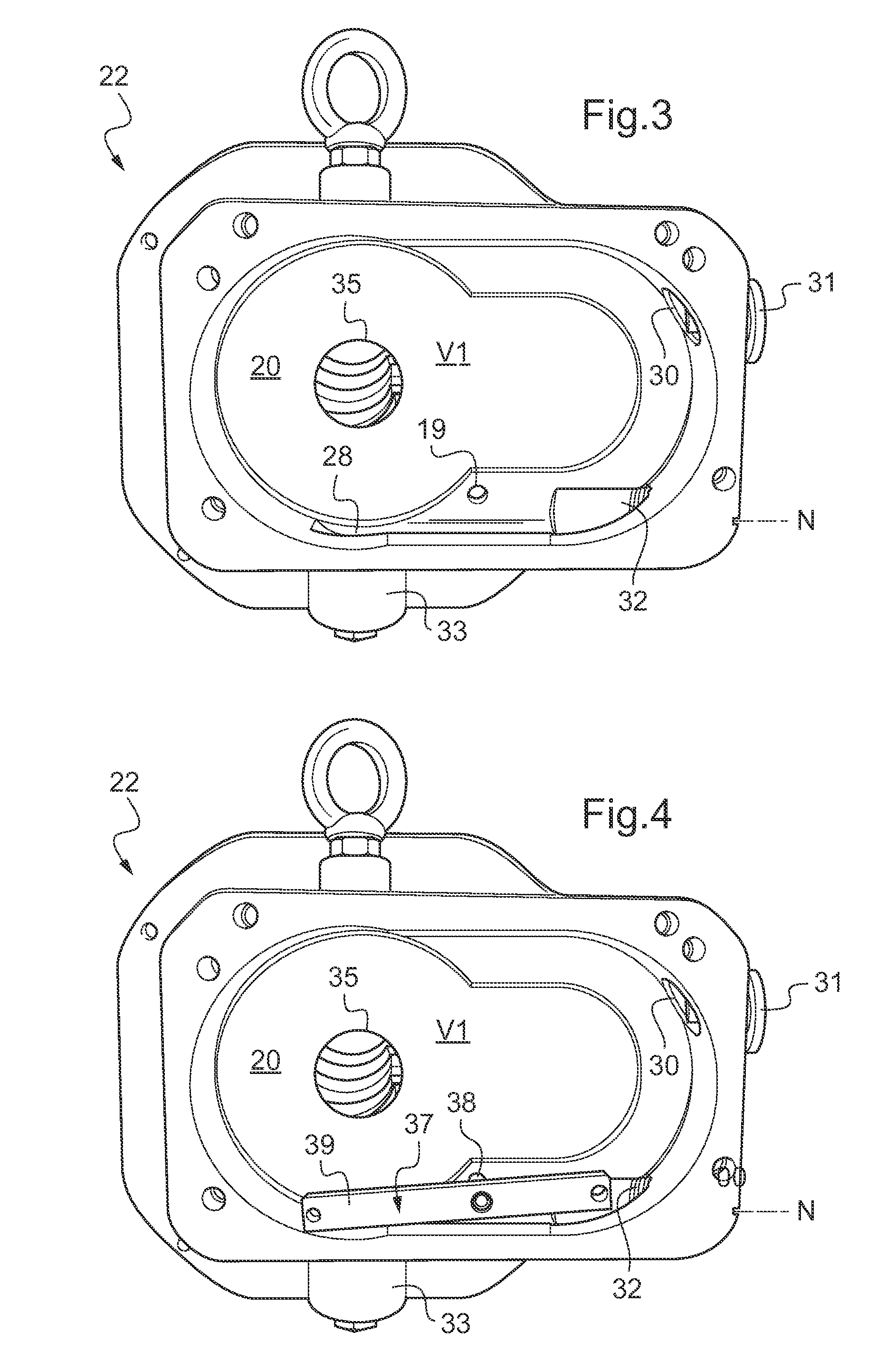
[0034]FIGS. 1 to 6 illustrate an exemplary embodiment of a dry type vacuum pump having two Roots type rotary lobe shaft. Naturally, the invention can also be applied to other types of dry-type vacuum pumps such as “claw”, spiral or screw type pumps or pumps based on any other similar principle.
[0035]The vacuum pump 1 has one or more series-mounted pumping stages 2 in which a gas to be pumped circulates from an admission inlet to a delivery outlet (not shown). The rotary shafts 3 (only one can be seen in FIG. 1) extend into the pumping stage 2 by rotary lobe rotors 4 and are driven on the delivery stage side in a motor drive compartment 5 of the vacuum pump 1. The pumping stage 2 is said to be “dry” because during operation the rotors 4 rotate inside the casing 6 in opposite directions without any mechanical contact between the rotors 4 and the casing 6 of the vacuum pump 1, enabling a total absence of lubricant.
[0036]The vacuum pump works horizontally as shown in FIG. 1, i.e. during...
PUM
 Abstract
Description
Claims
Application Information