Ultrasonic consumption meter with locking mechanism

a technology of ultrasonic consumption meter and locking mechanism, which is applied in the direction of volume/mass flow by mechanical effect, measurement devices, instruments, etc., can solve the problems delicate equipment of electronic consumption meter, and high risk of malfunction of electronic water meter, etc., and achieve the effect of low cos

Inactive Publication Date: 2014-11-25
APATOR MIITORS APS
View PDF33 Cites 29 Cited by
  • Summary
  • Abstract
  • Description
  • Claims
  • Application Information

AI Technical Summary

Benefits of technology

[0009]It is the object of this invention to provide a low cost, durable, and long-lived ultrasonic consumption meter protected against moisture, water and other substances coming from the surroundings and from the inside of the flow channel.
[0025]Especially advantageous is a housing impenetrated by electrical wires, as this lowers the risk of imperfections and leakage of water vapor and other hazardous substances into the housing.
[0027]The electronic circuit controls the emission and reception of ultrasonic signals, and converts the received signals to one or more usable values, depending on the flow in the flow channel. The values are shown on a display inside the housing, or it is transmitted to the outside of the housing by radio waves, magnetic pulses, electrostatic pulses, light pulses, or wires, or a combination of the six alternatives. Wireless transmission of values is preferred, so that electrical connections penetrating the housing can be avoided.
[0035]It is preferred that the one or more locking pins are moved into position in a movement parallel to the flow channel as this allows a larger distribution area for the forces that arises on the housing, when the pressure in the flow channel rises.

Problems solved by technology

Electronic consumption meters are delicate equipment that will suffer when placed in harmful environments, unless sensitive parts are well protected.
The main cause of dysfunction is due to corrosion of the electronic circuit or the components.
Other potentially harmful components in the environment could be aggressive gases or dust.
An electronic water meter is also in risk of being dysfunctional, if water from the flow channel penetrates the barrier between the flow channel and the electronics.
This is an effective solution, but unfortunately it is very costly, as sealed electrical connections are complex to manufacture.
This I not a very effective solution for long-term exposure of moisture or water, as known materials for potting of electronics has a relatively high degree of vapor penetration.
A water meter is typically used for many years, and in some cases it will even be submerged in water for very long periods.
Thus the risk of damage to the meter is high in these conditions.
This can be effective in some applications, but it is complex and expensive.

Method used


Image

  • Ultrasonic consumption meter with locking mechanism
  • Ultrasonic consumption meter with locking mechanism
  • Ultrasonic consumption meter with locking mechanism

Examples


Embodiment Construction

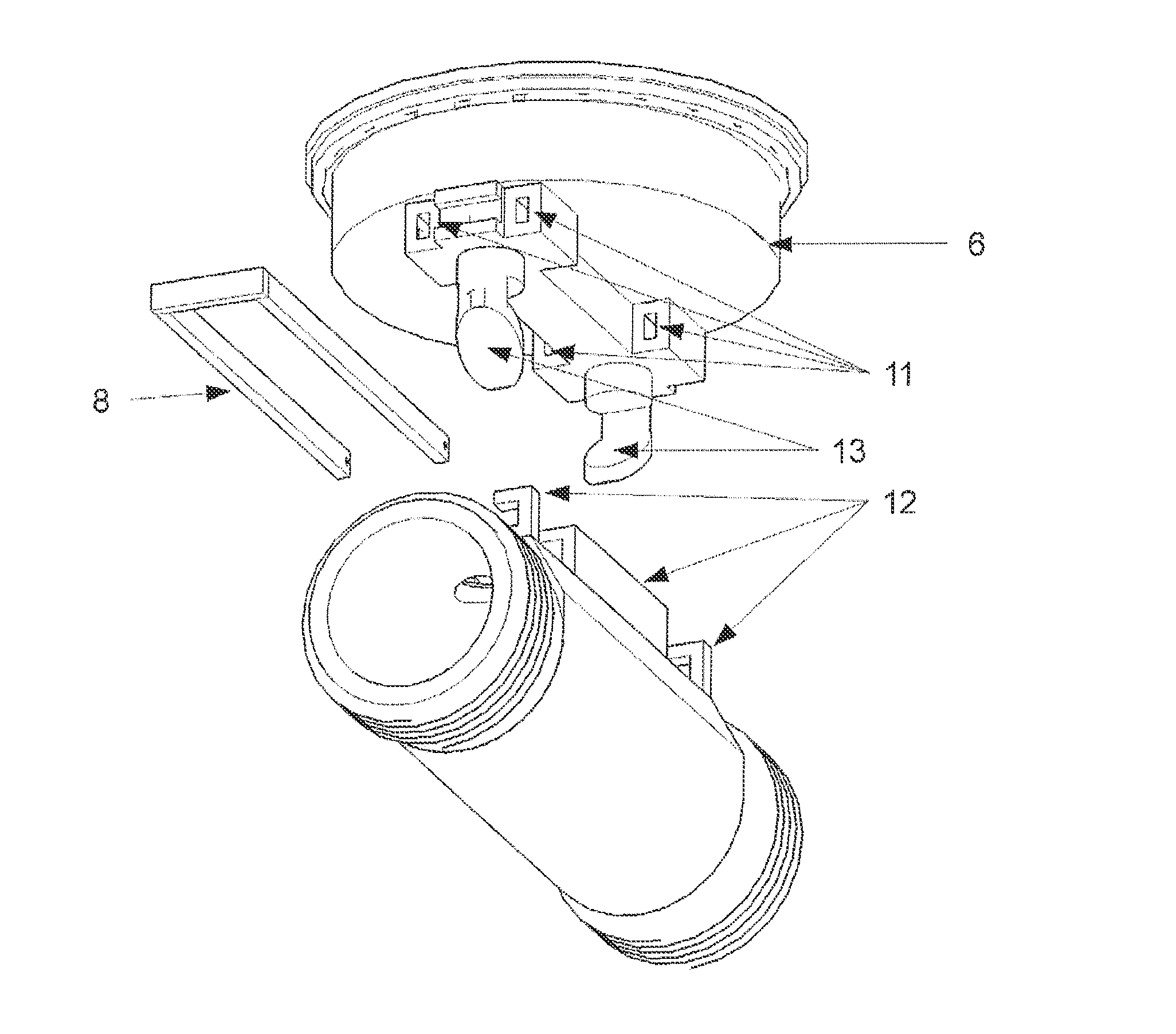
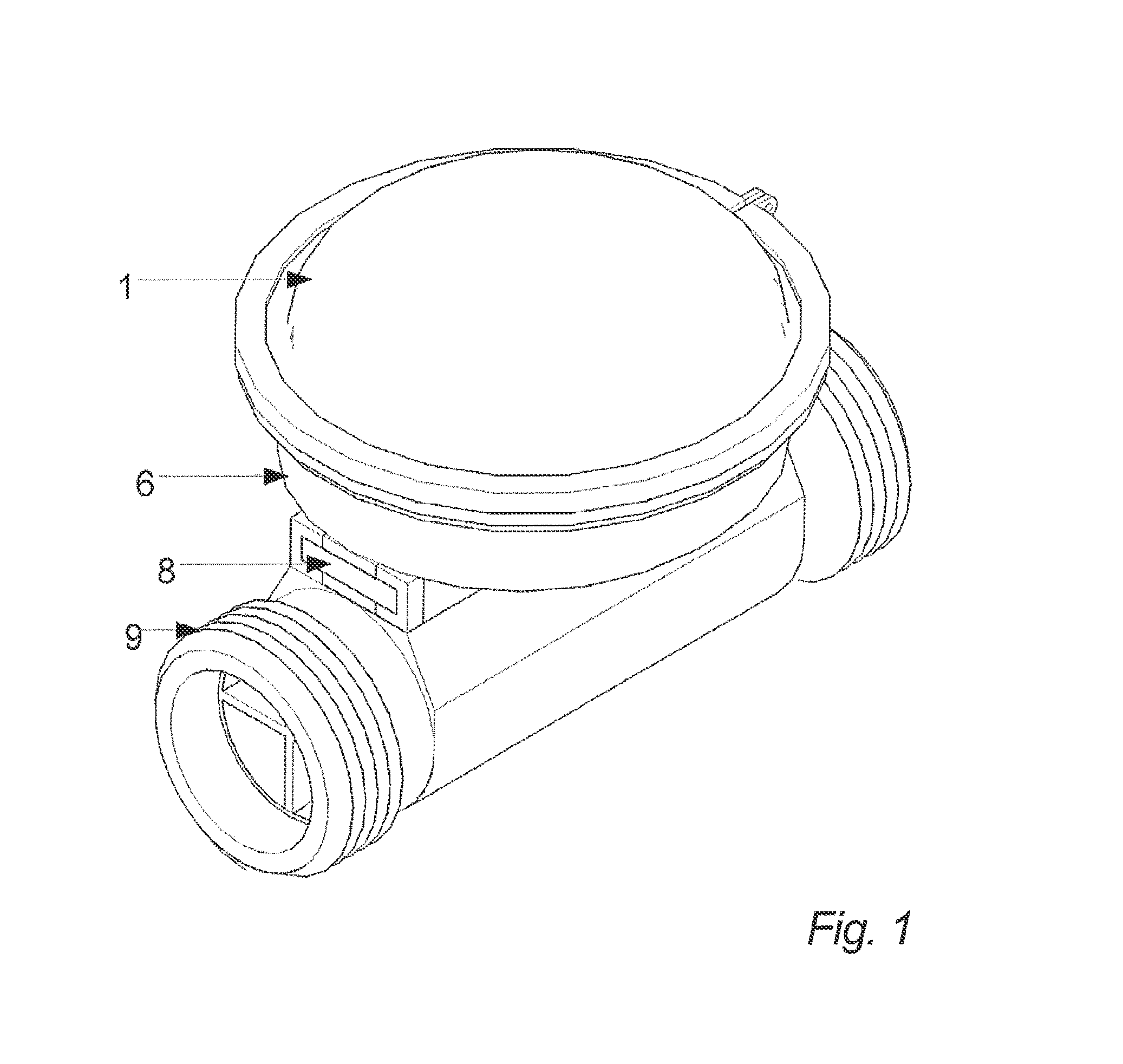
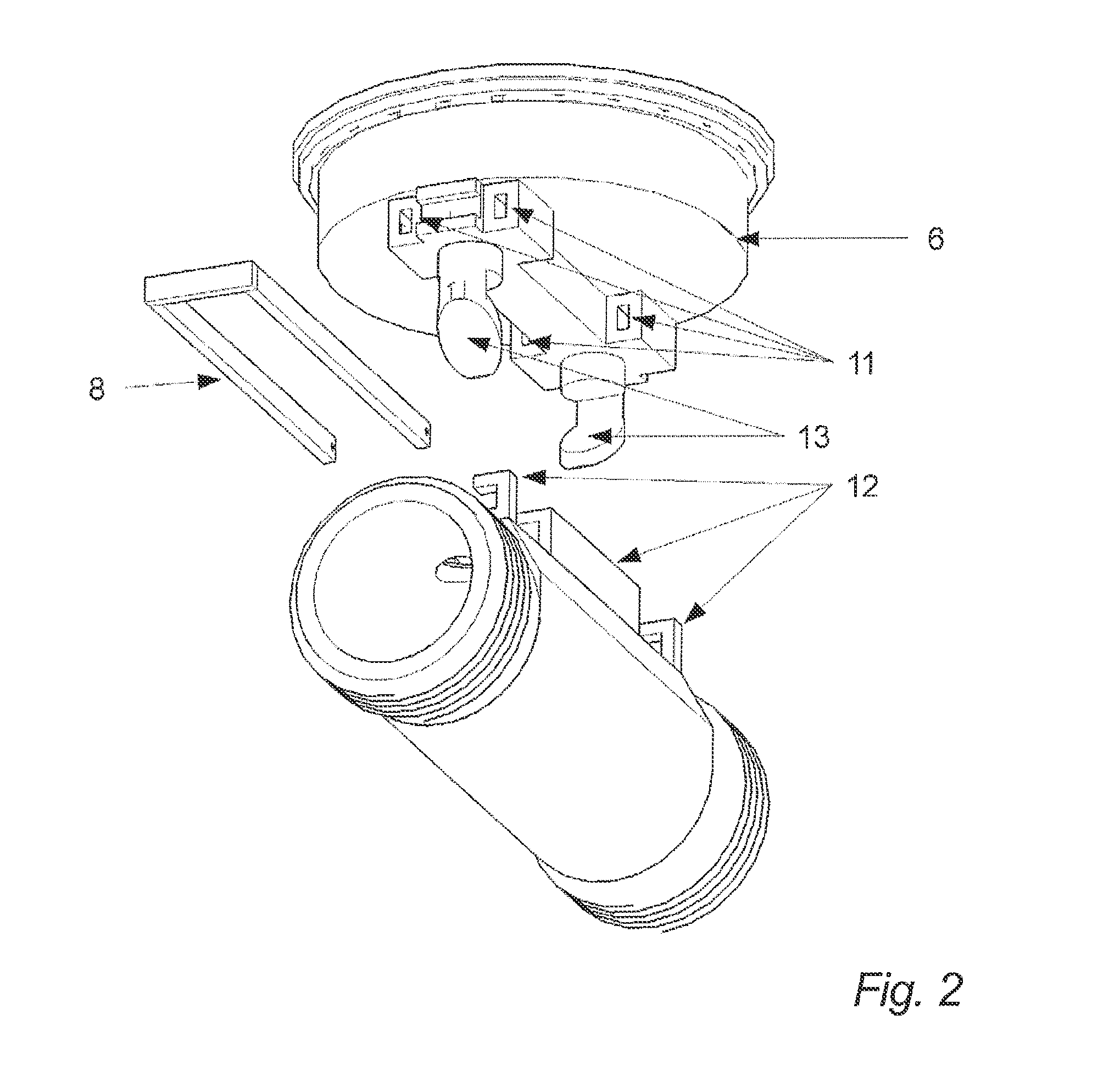
[0045]Referring now to the drawings, the elements are numbered as follows:

[0046](1) A lid. If a display or a front plate is present inside the housing, a transparent lid is advantageous. The lid is a part of the housing.

[0047](2) Front plate with information about the consumption meter, visible through the lid. The information can be of the following kind, but is not limited to: meter number, approval number, meter type, vendor name, utility name, meter size, or machine readable information such as barcodes or patterns.

[0048](3) Electronic circuit, comprising a Printed Circuit Board, electronic components, a power supply unit, such as a battery, and a display. In an advantageous embodiment, the interfaces for communication, such as optical communication, radio communication, or wired communication are a part of the electronic circuit. In addition to values derived from measurements, the display can optionally show information received via the communication interfaces. In an especial...


PUM


Abstract

An ultrasonic consumption meter includes an ultrasonic transducer for emitting and receiving ultrasonic waves, a flow channel, an electronic circuit for operating the meter, and a housing for the ultrasonic transducer and the electronic circuit. The housing is locked in position relative to the flow channel by a locking mechanism.

Description

FIELD OF THE INVENTION[0001]This invention concerns an ultrasonic consumption meter for metering fluid substances such as water or gas, especially a meter exposed to condensing conditions or other harmful environments.BACKGROUND OF THE INVENTION[0002]Electronic consumption meters are delicate equipment that will suffer when placed in harmful environments, unless sensitive parts are well protected. The main cause of dysfunction is due to corrosion of the electronic circuit or the components.[0003]As an example, an electronic meter for cold water is exposed to condensing water from the surrounding air, due to the temperature difference between the water in the meter and the potentially humid air. Other potentially harmful components in the environment could be aggressive gases or dust. An electronic water meter is also in risk of being dysfunctional, if water from the flow channel penetrates the barrier between the flow channel and the electronics.[0004]Several known ways exist for pr...

Claims


Application Information

Patent Timeline
Patent Type & Authority Patents(United States)
IPC IPC(8): G01F1/66G01F15/18G01F1/20G01F15/14
CPCG01F15/14G01F15/18G01F1/662G01F1/66
Inventor DRACHMANN, JENS
Owner APATOR MIITORS APS
Why Eureka
Try Eureka