Suspension bump stop and strut device

a bump stop and strut technology, applied in the direction of shock absorbers, bearing unit rigid supports, transportation and packaging, etc., can solve the problems of radial forces applied, particularly exposed to being splashed with water, and detrimental to the life of bearings, so as to increase the frictional torque of the bump stop and improve the sealing characteristics.

Inactive Publication Date: 2015-04-21
AB SKF
View PDF24 Cites 4 Cited by
  • Summary
  • Abstract
  • Description
  • Claims
  • Application Information

AI Technical Summary

Benefits of technology

[0012]An object of the present invention is a suspension bump stop the sealing characteristics of which are improved in all operating configurations, especially

Problems solved by technology

This results in radial forces applied by the spring to the lower cup of the suspension bump stop.
Because the suspension bump is under the bodywork of the vehicle, near the wheel, it is particularly exposed to being splashed with water.
However, the suspension bump stop of that document has the disadvantage of providing only a simple narrow passage between an upper cap and the lower support cap that supports the rolling bearing in order to seal the bump stop.
As a result, under certain conditions,

Method used


Image

  • Suspension bump stop and strut device
  • Suspension bump stop and strut device
  • Suspension bump stop and strut device

Examples


Embodiment Construction

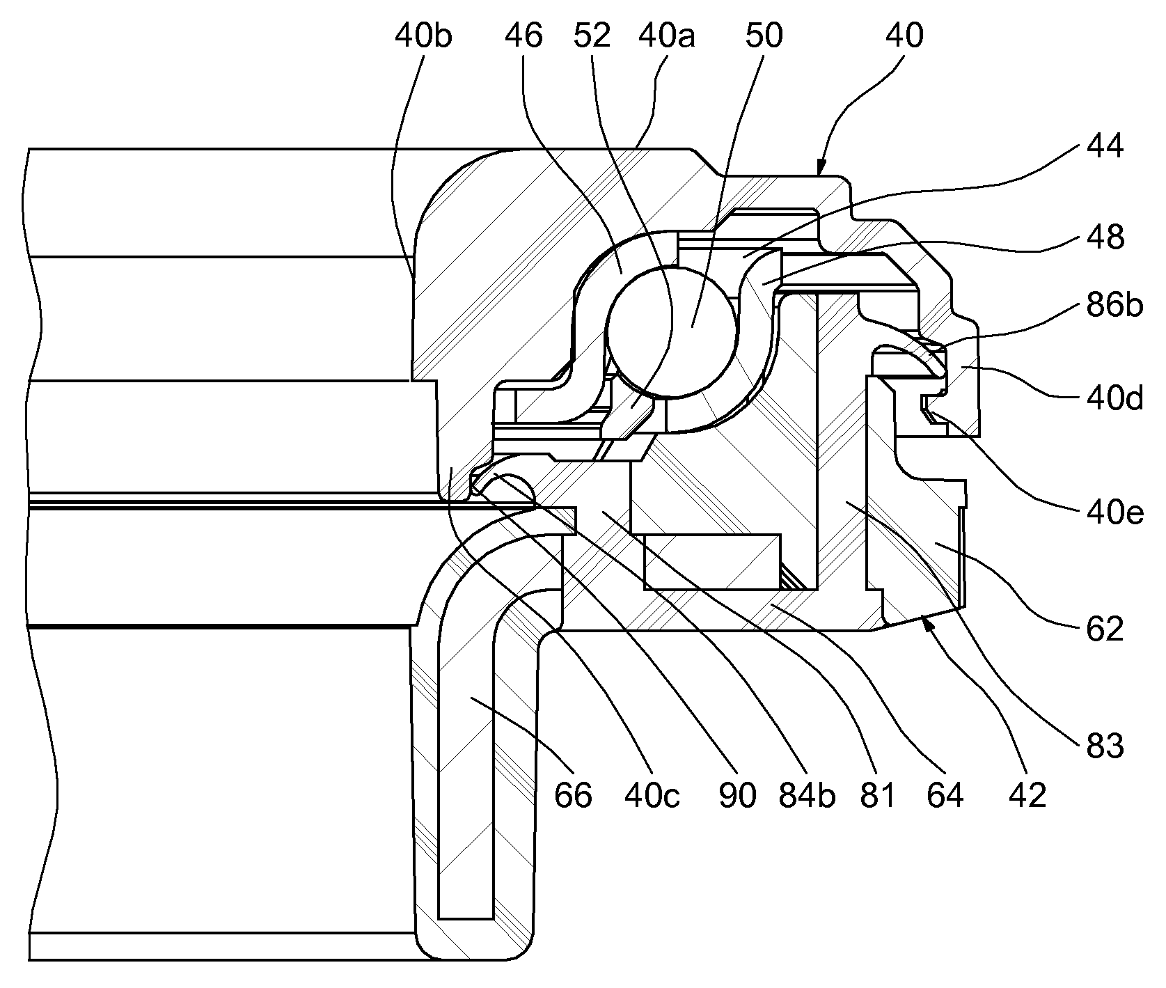
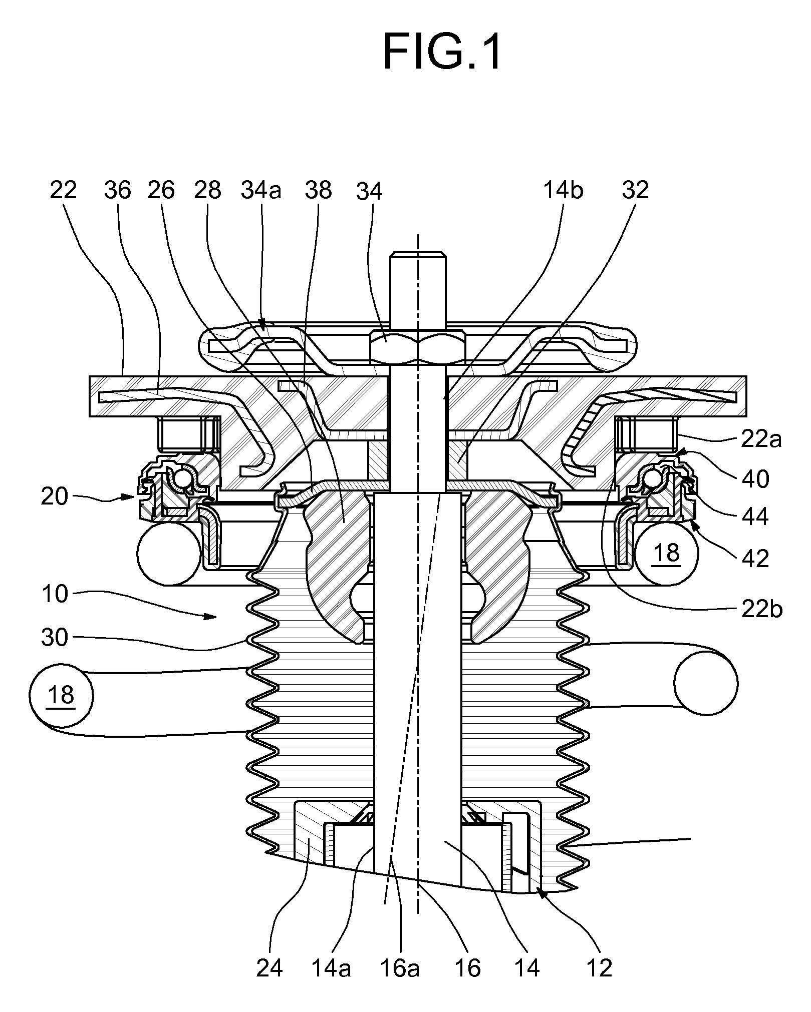
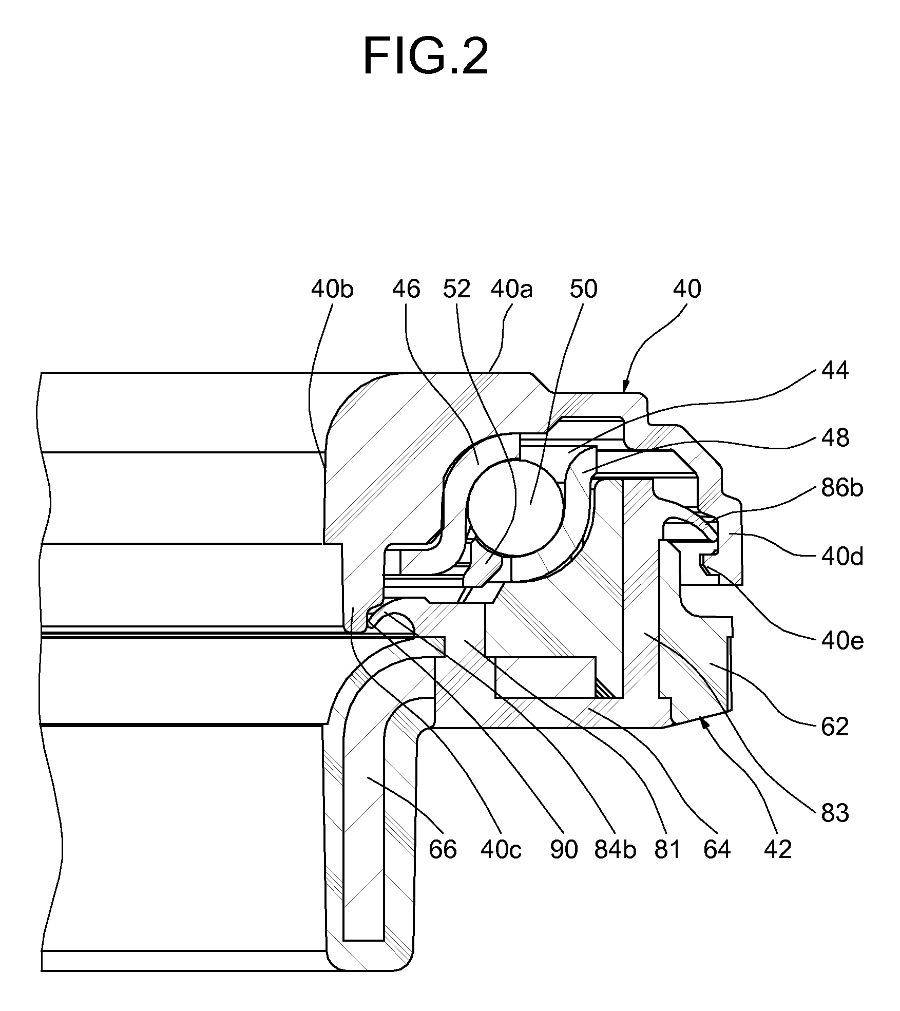
[0030]As can be seen from FIG. 1, a strut referenced 10 overall is provided with a shock absorber 12 comprising a rod 14 of axis 16, with a spring 18, with a suspension bump stop 20 mounted around the rod 14 and with a filtering elastic block 22 positioned between the bump stop 20 and the bodyshell (not depicted) of a motor vehicle in which the strut 10 is mounted. FIG. 1 also depicts the line of force 16a exerted by the spring 18. This line of force 16a makes an angle with the axis 16 of the suspension device because of the way (not depicted in the figure) the lower end of the spring 18 is mounted on a seat that is inclined with respect to the axis 16 as described for example in patent application FR 2 783 204.

[0031]The shock absorber 12 also comprises a shock absorber cylinder 24 depicted in part. The rod 14 of the shock absorber has a large-diameter portion 14a, a small-diameter portion 14b, the said portions being separated by a radial shoulder 14c. The shock absorber 12 further...


PUM


Abstract

The suspension bump stop device comprises a rolling bearing (44) that forms an axial bump stop, equipped with an upper ring (46), with a lower ring (48) and with a plurality of rolling elements positioned between the rings, the upper and lower rings being supported respectively by an upper cup (40) and a lower cup (42), the lower cup forming a bearing means for a suspension spring (18), at least one sealing lip being provided on one of the cups so that it bears against a bearing surface portion of the other cup. The bearing surface portion is substantially cylindrical, the sealing lip being directed downwards away from the rolling bearing and bearing with radial interference against the said surface portion, the said substantially cylindrical surface portion being connected towards the top to a shoulder against which the lip can bear if the two cups become radially eccentric relative to one another.

Description

BACKGROUND OF THE INVENTION[0001]The present invention relates to the field of suspension bump stop devices used in particular in motor vehicles in the suspension struts of the steered wheels.[0002]The invention relates more specifically to a suspension bump stop device comprising an upper ring and a lower ring between which rolling elements, for example balls or rollers, are positioned. The upper and lower rings are generally mounted in contact with lower and upper bearing or support pieces, such as caps or cups. The upper and lower support cups form a housing for the rings of the rolling bearing and provide the interface between the said rings and the surrounding elements.[0003]A suspension bump stop is positioned in the upper part of the suspension strut between the vehicle bodyshell and a suspension spring. The spring is installed around the piston rod of a shock absorber the end of which is connected to the vehicle bodyshell via an elastic block that filters out vibrations. The...

Claims


Application Information

Patent Timeline
IPC IPC(8): F16F7/00B60G15/06F16C19/10F16C33/76F16C35/04
CPCB60G15/068F16C19/10F16C33/761F16C35/04B60G2204/128B60G2204/418B60G2204/45021F16C2326/05
Inventor VIAULT, SAMUELLIVERATO, YVES-ANDREBRULARD, CEDRICHECK, GUY
Owner AB SKF
Why Eureka
Try Eureka