
Rack bushing for rack and pinion steering assembly

a steering assembly and rack bushing technology, applied in mechanical equipment, transportation and packaging, gearing, etc., can solve the problems of less capable of accepting high side loads and more expensive bushing assemblies, and achieve the effects of low cost, easy manufacturing and assembly, and light weigh

Active Publication Date: 2008-07-22
TRW AUTOMOTIVE US LLC
View PDF16 Cites 19 Cited by
  • Summary
  • Abstract
  • Description
  • Claims
  • Application Information

AI Technical Summary

Benefits of technology

[0010]The present invention advantageously provides a light weight and cost effective rack bushing that is relatively easy to fabricate and assemble.
[0011]Another advantage of an embodiment of the present invention is that the rack bushing assembly is strong enough to withstand the wide range of high load conditions it may encounter during vehicle operation, while maintaining good sealing characteristics with the rack housing and the rack.

Problems solved by technology

But such bushing assemblies can be more expensive than is desired and require these separate parts for the bushing assembly.
While these plastic bushings are more cost-effective than the metal bushings, they are less capable of accepting the high side loads that may be induced in the bushing during vehicle operation.
While these voids are helpful in reducing the overall weight of the rack bushing assembly, the corners of these voids tend to create stress risers in the bushing.

Method used


Image

  • Rack bushing for rack and pinion steering assembly
  • Rack bushing for rack and pinion steering assembly
  • Rack bushing for rack and pinion steering assembly

Examples


Embodiment Construction

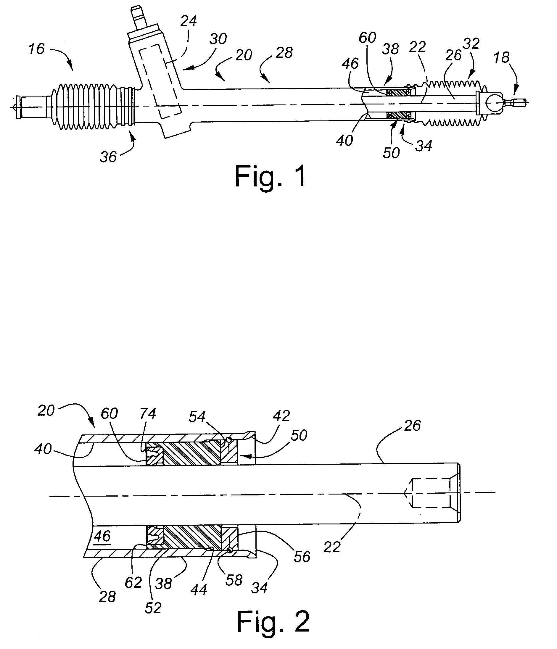
[0023]FIGS. 1-2 illustrate a portion of a steering assembly, indicated generally at 16, for use in a vehicle (not shown). The steering assembly 16 is connected with a pair of steerable vehicle wheels (not shown) in a known manner by a steering linkage 18 at one end of the steering assembly 16 and by a similar steering linkage (not shown) at the other end of the steering assembly 16. The steering assembly 16 includes a housing 20 defining a longitudinally oriented rack axis 22, a pinion 24, and a rack 26 that has the same rack axis as the housing 20. The housing 20 includes a longitudinally extending rack portion 28 and a transversely extending pinion portion 30. The rack 26 extends through the rack portion 28. The pinion 24 is located in the pinion portion 30 of the housing 20 and engages with the rack 26 in a known manner. A bellows 32 encircles and encloses the portion of the rack 26 extending from the housing 20. The bellows 32 mounts around and is secured to the housing 20 in a ...


PUM


Abstract

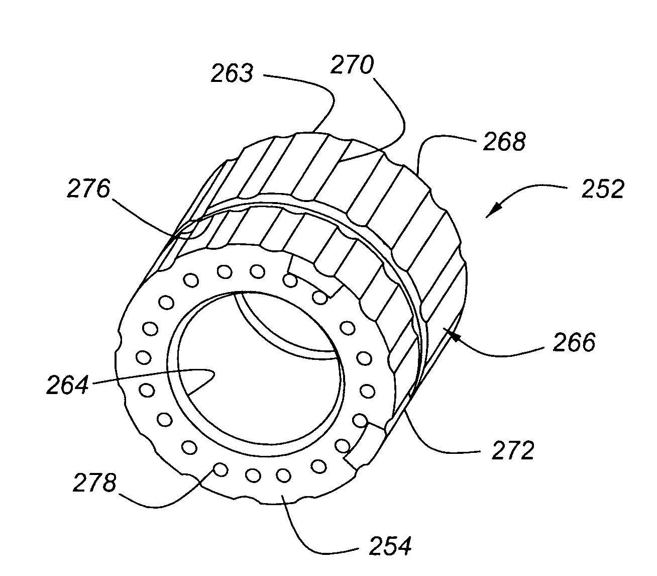
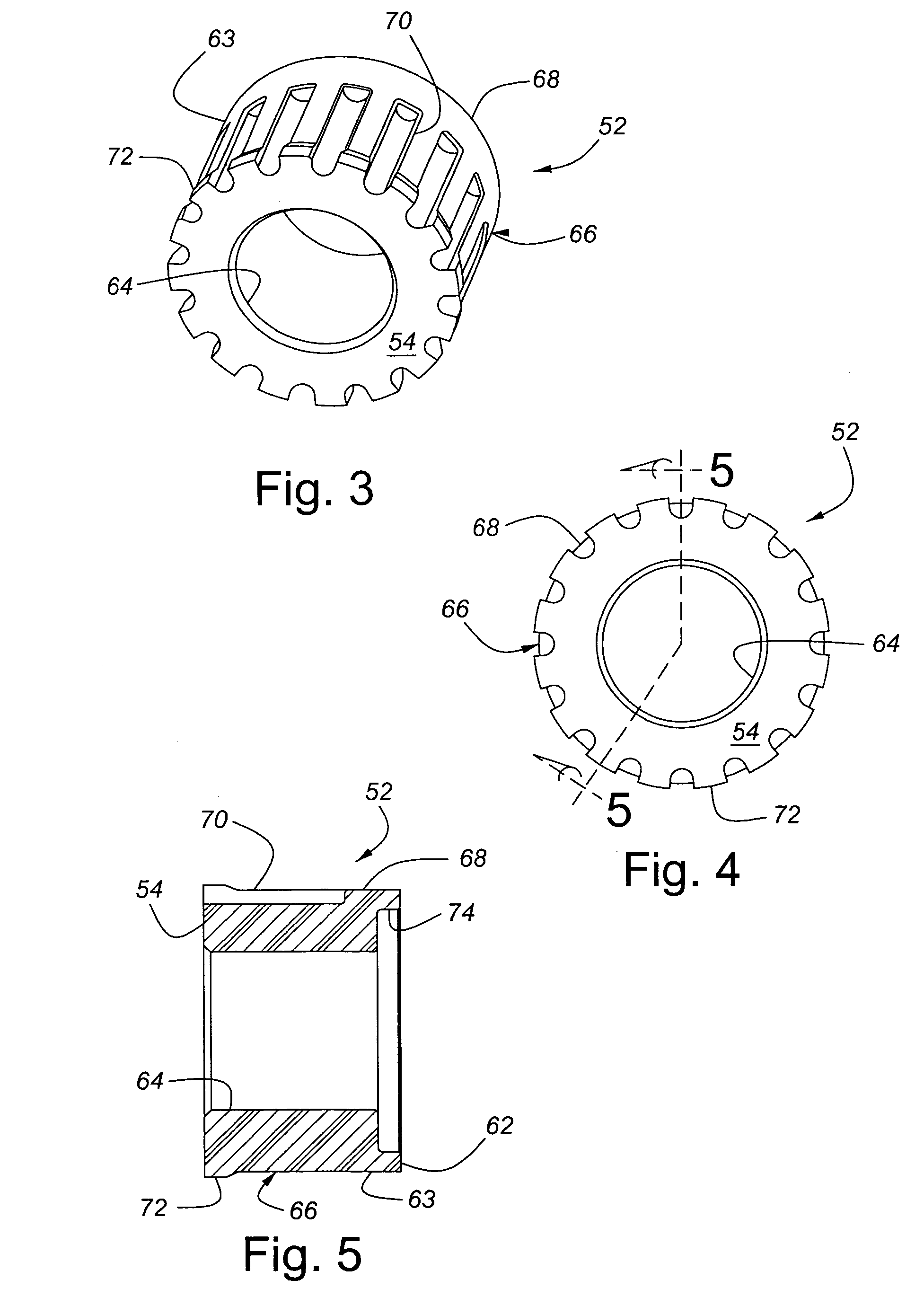
The invention contemplates a rack bushing and a rack and pinion steering assembly for use in a vehicle that includes such a rack bushing. The steering assembly may include a housing having a tubular rack portion with a tubular end, a rack mounted in the tubular rack portion and extending out of the tubular end, and a rack bushing mounted in the rack portion around the rack. The rack bushing includes a generally annular main body portion having a generally cylindrical inner surface centered about the axis and supporting the rack, an outer surface centered about the axis and including a generally cylindrical main surface adapted to engage the tubular end of the housing, and a first end and an opposed second end. The rack bushing may include a plurality of bores extending within the main body axially from the first end a portion of the way toward the second end. The rack bushing may also include a plurality of channels extending parallel to the axis, recessed in, and spaced circumferentially around the outer surface.

Description

BACKGROUND OF INVENTION [0001]The present invention relates generally to automotive vehicle steering systems and, in particular, to a rack bushing used in a rack and pinion steering assembly.[0002]A typical hydraulic rack and pinion power steering assembly used in a vehicle includes a rack that extends axially through a hydraulic chamber inside a hydraulic housing. The ends of the rack project axially outward from each end of the housing and are connected with steering linkages that connect to steerable vehicle wheels. A piston is fixed to the rack within the hydraulic chamber. Rotation of the vehicle steering wheel actuates a hydraulic valve and causes hydraulic fluid under pressure to act against the piston. The force exerted by the hydraulic fluid moves the piston within the housing, causing the rack to move axially. The axial movement of the rack moves the steering linkages that, in turn, cause the corresponding vehicle wheels to turn.[0003]To prevent hydraulic fluid from flowin...

Claims


Application Information

Patent Timeline
Patent Type & Authority Patents(United States)
IPC IPC(8): F16C33/02
CPCB62D5/22F16C29/02F16J15/3268F16J15/3216Y10T74/18776B62D3/12
Inventor HARER, DENNIS F.ROLINE, ERIC A.ALLEN, JR., WILLIAM E.
Owner TRW AUTOMOTIVE US LLC
Learn More