Electrical connector

a technology of electrical connectors and connectors, applied in the direction of electrical discharge lamps, securing/insulating coupling contact members, coupling device connections, etc., can solve the problems of relatively high cost, vibration of electrical connectors, etc., and achieve the effect of reducing manufacturing and assembly costs and minimizing the number of components of electrical connectors

Inactive Publication Date: 2001-02-06
CINCH CONNECTORS
View PDF45 Cites 17 Cited by
  • Summary
  • Abstract
  • Description
  • Claims
  • Application Information

AI Technical Summary

Benefits of technology

A general object of the present invention is to provide an electrical connector which can withstand environmental conditions for the particular application. Another object of the invention is to provide an electrical connector which reduces the manufacturing and assembly costs. An additional object of the invention is to provide an electrical connector which minimizes the number of components for the electrical connector.

Problems solved by technology

In addition, such electrical connectors are subjected to vibration from the engine or the movement of the vehicle.
This process may be performed by an individual and therefore, can be relatively expensive.

Method used


Image

  • Electrical connector
  • Electrical connector
  • Electrical connector

Examples


Embodiment Construction

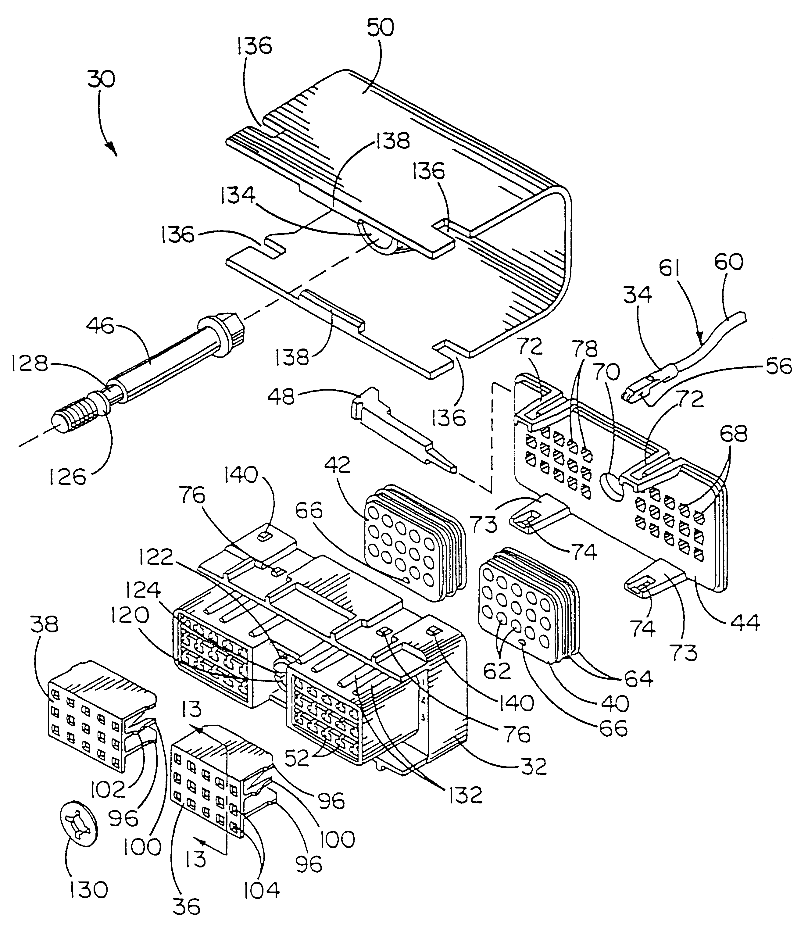
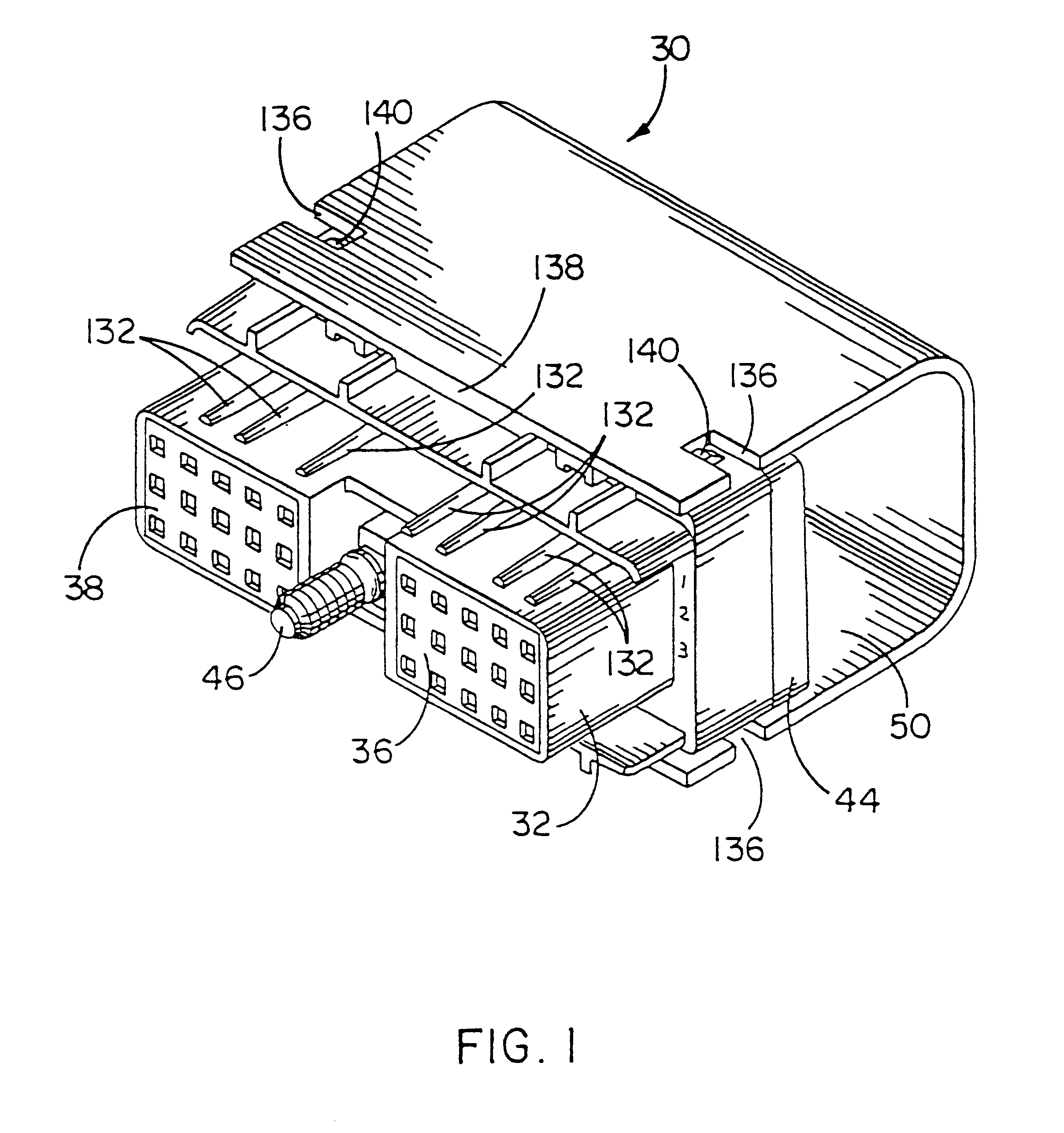
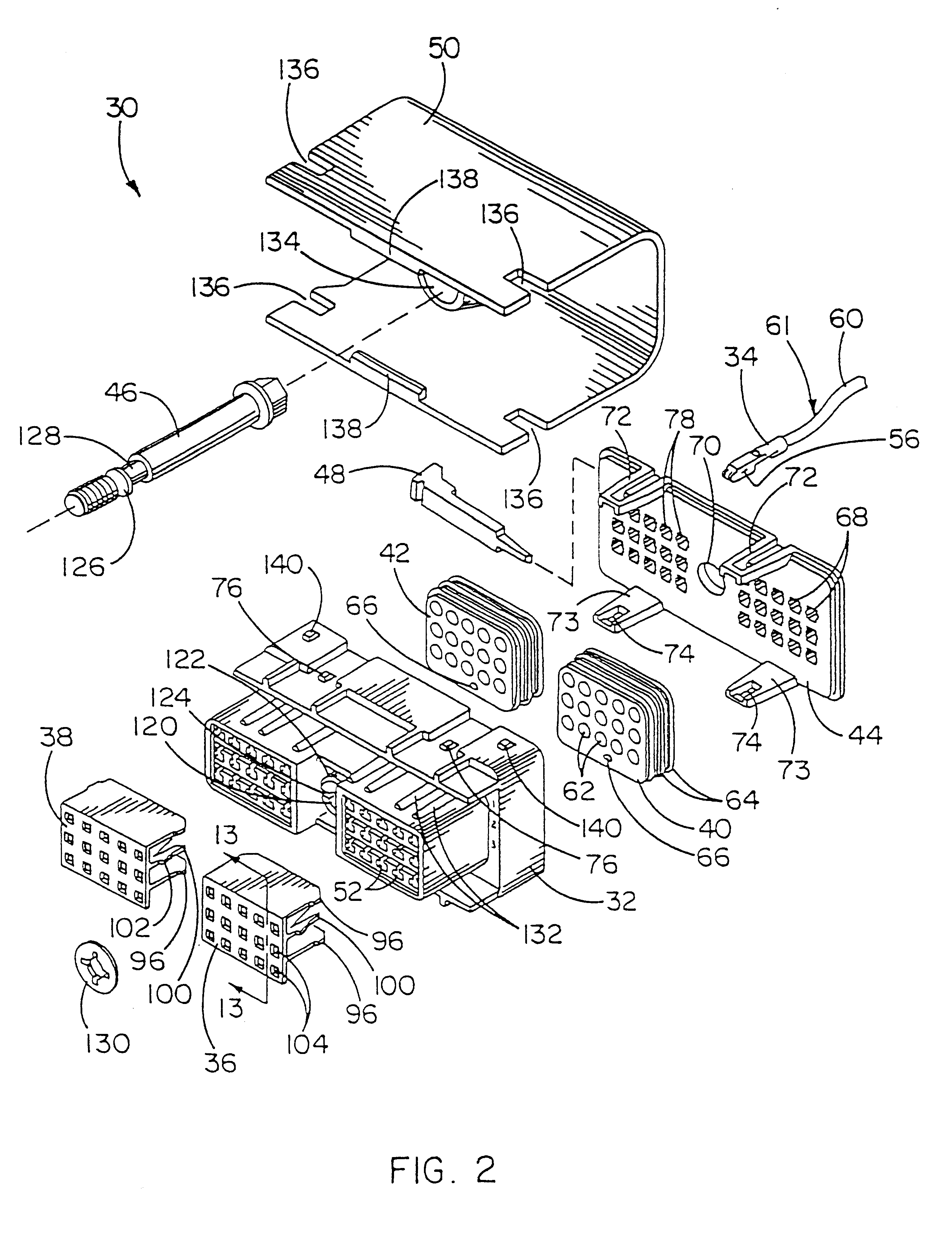
An electrical connector 30 constructed in accordance with the teachings of the invention is illustrated in FIG. 1. As shown in FIG. 2, the electrical connector 30 may include an insulator housing 32, a contact 34, a secondary lock 36, 38, grommets 40, 42, backplate 44, bolt 46, contact removal tool 48, and splash guard 50.

The insulator housing 32 includes openings 52 which receive the contacts 34. The openings 52 include grooves 54 which are shown in FIGS. 4A and 6. As will be discussed below, the grooves 54 will engage protrusions 56 on the contacts 34 to align and support the contacts 34.

Referring to FIG. 8, the contact 34 includes protrusions 56 and opening 58. The contact 34 is crimped onto the wire 60 to create the contact and wire assembly 61. The contact 34 is attached to the wire 60 either manually or by use of an automatic wire stripping and contact crimping machine. In order to facilitate use of the machine, the contacts 34 are available in a strip and positioned in side-b...


PUM


Abstract

The electrical connector may include a housing, a contact, a secondary lock, a grommet, a backplate, a bolt, a contact removal tool, and a splash guard. The housing includes openings which receive the contacts. The grommets are positioned in cavities at the rear of the housing. The housing and backplate are designed so that the grommets are subjected to compressive forces in order to enhance the sealing characteristic of the grommets. As the contact is inserted, a locking tab engages an opening in the contact and prevents the contact from being removed from the housing. The secondary locks will increase the retention of the contact in the electrical connector. In addition, the secondary lock may include a feature which permits the partial insertion and retention of the secondary lock prior to insertion of the contact. The secondary lock also assures that the contacts have been properly inserted. The electrical connector may also include a splash guard which would assist in deflecting water from the rear of the electrical connector. The electrical connector may also include a removal tool which may be used to remove contacts from the electrical connector. The removal tool can be stored in the backplate or the housing.

Description

The invention relates to an electrical connector and more particularly to an electrical connector which can be used in exterior environmental conditions.Electrical connectors are used in exterior environments to connect wires with various devices. The exterior environments may include agricultural equipment, construction equipment or other vehicles which may be exposed to the weather, such as, moisture and temperature extremes. In addition, such electrical connectors are subjected to vibration from the engine or the movement of the vehicle. Thus, the electrical connector should withstand these operating conditions.In addition, it is necessary to attach the electrical connector to the individual wires. Specifically, the individual wire is attached to an electrical contact. The electrical contact with the attached wire is then assembled into the housing for the electrical connector. This process may be performed by an individual and therefore, can be relatively expensive.OBJECTS OF TH...

Claims


Application Information

Patent Timeline
Patent Type & Authority Patents(United States)
IPC IPC(8): H01R13/52H01R13/436H01R13/422H01R43/22H01R13/621H01R43/20H01R13/42H01R13/633
CPCH01R13/4364H01R13/5208H01R13/4223H01R13/621H01R43/22Y10S439/902
Inventor PACINI, LOUIS S.SHAH, ARUN J.
Owner CINCH CONNECTORS
Why Eureka
Try Eureka