Method of manufacturing flat display panels of different sizes from a common base substrate

a technology of flat display and base substrate, which is applied in the direction of lighting and heating equipment, identification means, instruments, etc., can solve the problems of complex manufacturing line and large investment, and achieve the effect of reducing the size of the manufacturing line, reducing the influence of manufacturing apparatus parts, and reducing the cost of production and quality

Inactive Publication Date: 2007-09-25
KK TOSHIBA
View PDF35 Cites 48 Cited by
  • Summary
  • Abstract
  • Description
  • Claims
  • Application Information

AI Technical Summary

Benefits of technology

[0011]Another object of this invention is to provide a manufacturing method such that interference of manufacturing equipment with processes can be reduced and that the frame width of flat display apparatuses can be narrowed.
[0015]Since the second regions that are used to hold the manufacturing apparatuses are distant from the first region, moreover, bad influences of manufacturing apparatus portions on the first region can be eliminated, and the yield of production and quality of products can be improved. Further, a so-called frame region outside an image display region part of the flat display apparatus, which is obtained by cutting and separating substrate portions that are unnecessary for the flat display apparatus, can be minimized in size. Thus, there may be obtained a manufacturing method that can realize flat display apparatuses with high commercial value.

Problems solved by technology

If various sizes that are required by the market are to be covered by the manufacture, however, the manufacturing line may be complicated or the manufacturing equipment must be remodeled or, in some cases, changed completely on each occasion, thus requiring a vast investment.

Method used


Image

  • Method of manufacturing flat display panels of different sizes from a common base substrate
  • Method of manufacturing flat display panels of different sizes from a common base substrate
  • Method of manufacturing flat display panels of different sizes from a common base substrate

Examples


example 1

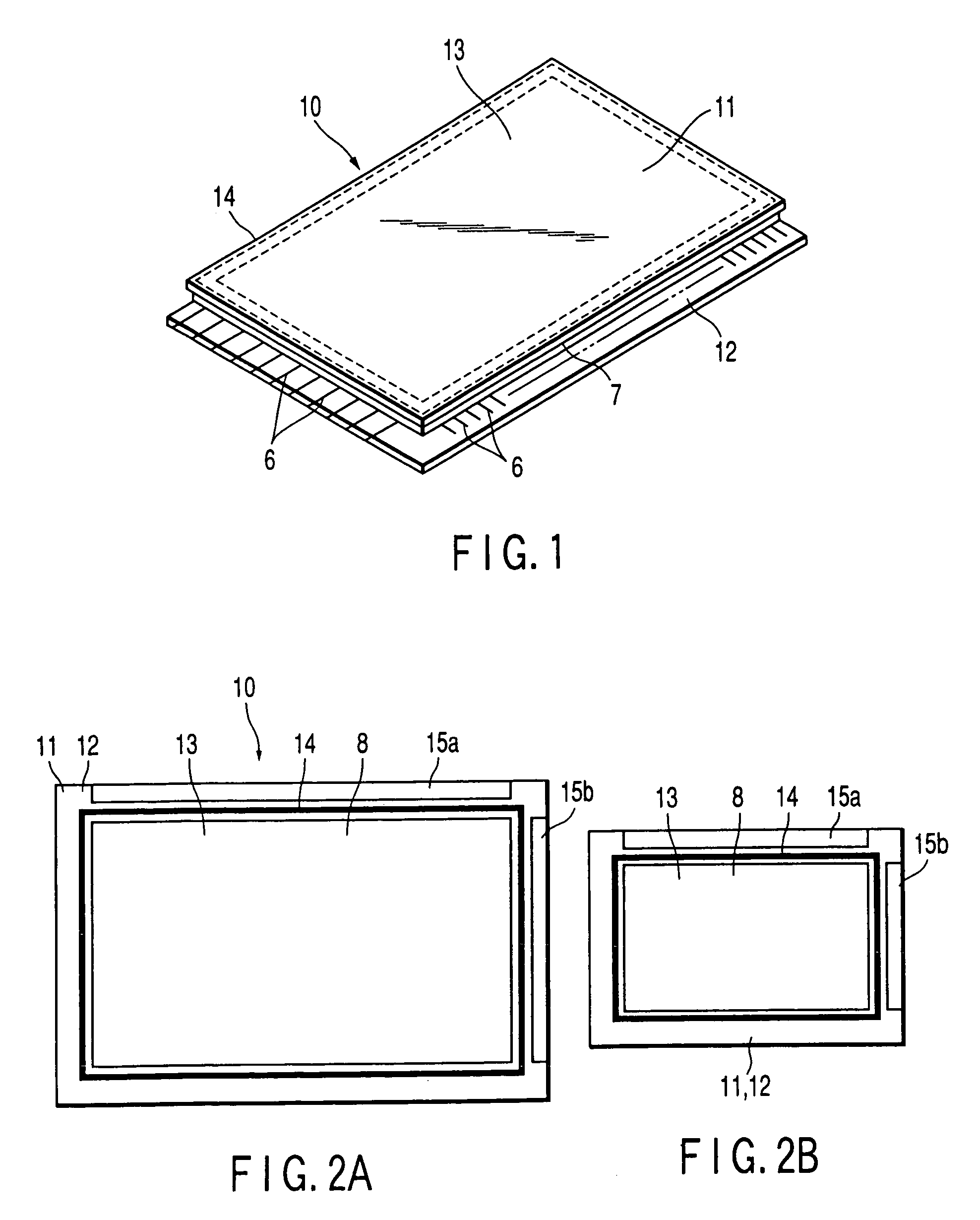
[0051]The following is a description of a case in which a 35-inch FED is manufactured as FEDs of different sizes ranging from 30 to 40 inches are manufactured in a common manufacturing line.

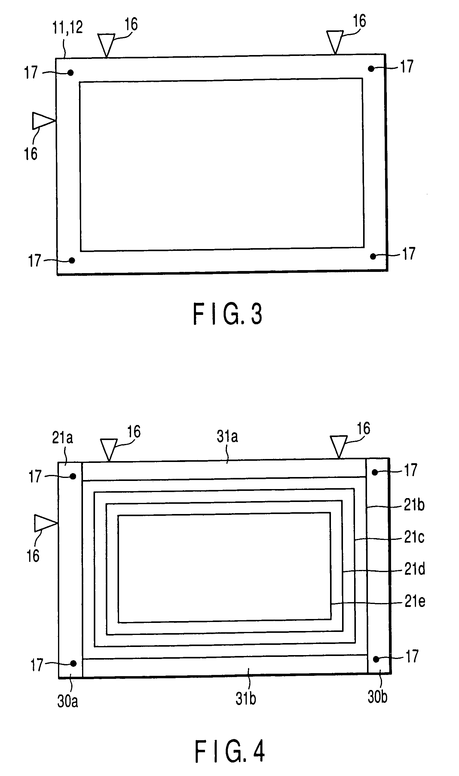
[0052]First, the rectangular flat substrate 21a is prepared as a common flat substrate, as shown in FIG. 5. The flat substrate 21a is given a size of 42 inches, for example.

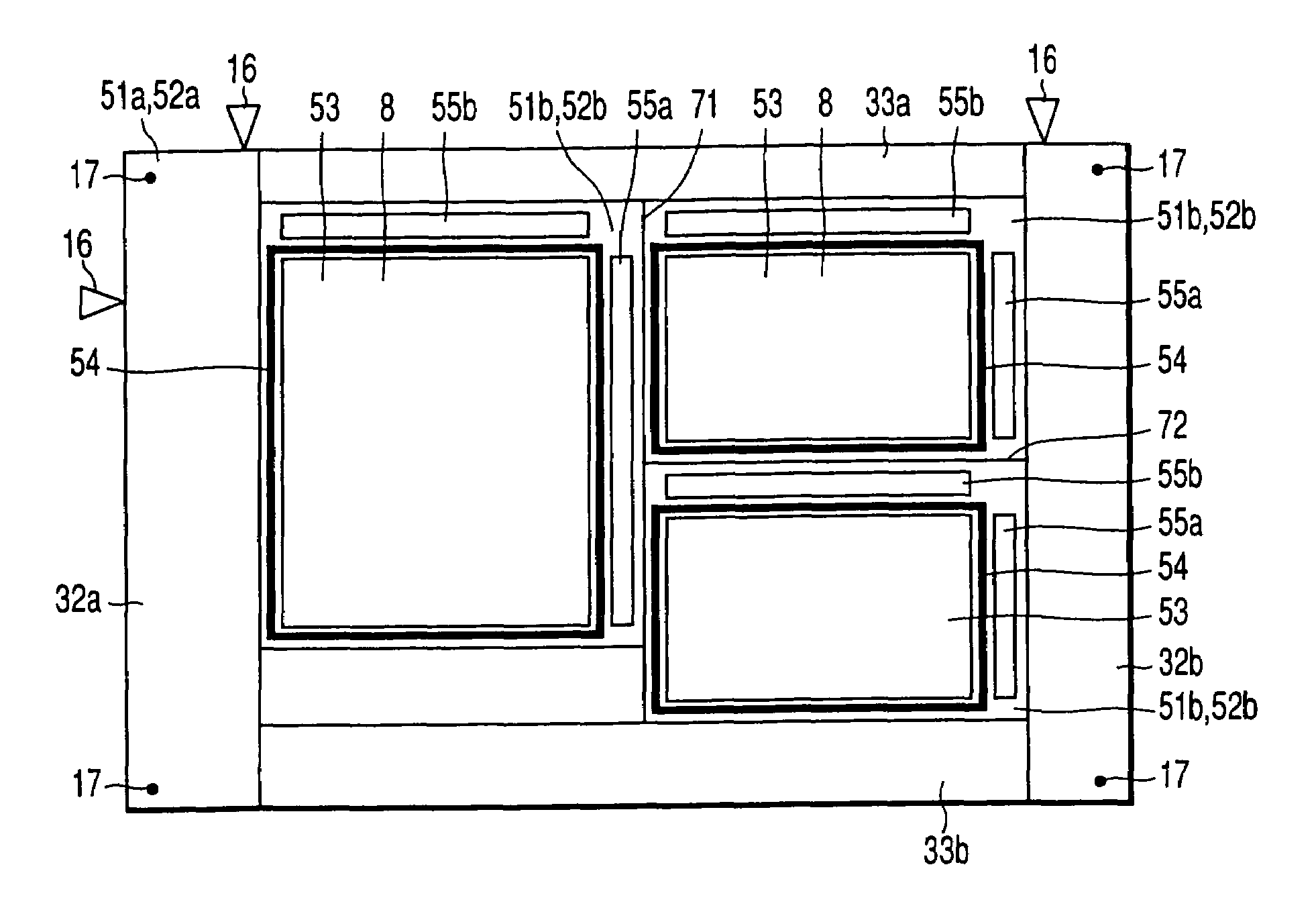
[0053]Subsequently, the rectangular first region 21b to be used for the 35-inch FED is set on the flat substrate 21a, and this first region is worked as desired. Thus, a rectangular image display region 23 having the image display pattern 8, a sealing region 24 in the form of a rectangular frame situated around the image display region, mounting regions 25a and 25b situated outside the sealing region, and other necessary regions for the flat display apparatus are intensively formed in the first region 21b.

[0054]The first region 21b is set in the central portion of the flat substrate 21a. Thereupon, the second regions 30a, 30b...

example 2

[0066]According to Example 2, as shown in FIGS. 6A and 6B, various manufacturing processes are carried out with a first region 21b set near one corner portion of a flat substrate 21a and with use of only two second regions 30a and 31a. According to the present example, there are few cut portions, so that the manufacturing efficiency can be improved. This example shares other configurations with the foregoing example, and a detailed description of them is omitted.

example 3

[0067]According to Example 3, as shown in FIGS. 7A and 7B, second regions 30a, 30b, 31a and 31b are formed so that a frame region of a first region 21b that is situated outside a sealing region 14 is asymmetric, in order to make the first region as compact as possible. More specifically, the other two side portions of the frame region are made narrower than those two side portions on which mounting regions 25a and 25b are formed.

[0068]According to this manufacturing method, differences that are attributable to differences in size between display apparatuses to be manufactured involve differences in cutting specifications only. Therefore, this example shares load on the manufacturing processes with the other examples even though cutting and the like are made so that the frame region is asymmetric. According to the present example, which shares the same functions and effects with the foregoing alternative examples, the frame of a resulting FED can be further narrowed. This example sha...


PUM

PropertyMeasurementUnit
sizeaaaaaaaaaa
sizesaaaaaaaaaa
sizeaaaaaaaaaa

Abstract

In a method of a manufacturing flat display apparatuses by working flat substrates, a flat substrate is prepared having a first region which is used as a flat display apparatus and a second region outside the first region. After the first region is worked as desired, the second region is cut and separated from the flat substrate.

Description

CROSS-REFERENCE TO RELATED APPLICATIONS[0001]This is a Continuation Application of PCT Application No. PCT / JP02 / 13526, filed Dec. 25, 2002, which was not published under PCT Article 21 (2) in English.[0002]This application is based upon and claims the benefit of priority from prior Japanese Patent Application No. 2001-398183, filed Dec. 27, 2001, the entire contents of which are incorporated herein by reference.BACKGROUND OF THE INVENTION[0003]1. Field of the Invention[0004]This invention relates to a manufacturing method for flat display apparatuses.[0005]2. Description of the Related Art[0006]Recently, various flat display apparatuses have been developed as a next generation of lightweight, thin image display apparatuses to replace cathode-ray tubes (hereinafter referred to as CRT). These known flat display apparatuses include a liquid crystal display (hereinafter referred to as LCD), plasma display panel (hereinafter referred to as PDP), field emission display (hereinafter referr...

Claims


Application Information

Patent Timeline
Patent Type & Authority Patents(United States)
IPC IPC(8): H01J9/24H01J9/26H01J9/42G02F1/13G02F1/1333G09F9/00H01J9/39
CPCG02F1/1333G02F1/133351H01J9/241G02F2001/133354G02F1/13452G02F1/133354G02F1/13H01J9/24
Inventor YOKOTA, MASAHIROTAKENAKA, SHIGEO
Owner KK TOSHIBA
Why Eureka
Try Eureka