

Disk drive enclosure
a technology for enclosures and disk drives, applied in the direction of machine supports, electric apparatus casings/cabinets/drawers, instruments, etc., can solve the problems of increased heat, increased noise, and increased power consumption of disk drives, so as to reduce noise, reduce noise, and reduce noise
- Summary
- Abstract
- Description
- Claims
- Application Information
AI Technical Summary
Benefits of technology
Problems solved by technology
Method used
Image

Examples
Embodiment Construction
The following detailed description should be read in conjunction with the attached drawing in which similar reference numbers indicate similar structures.
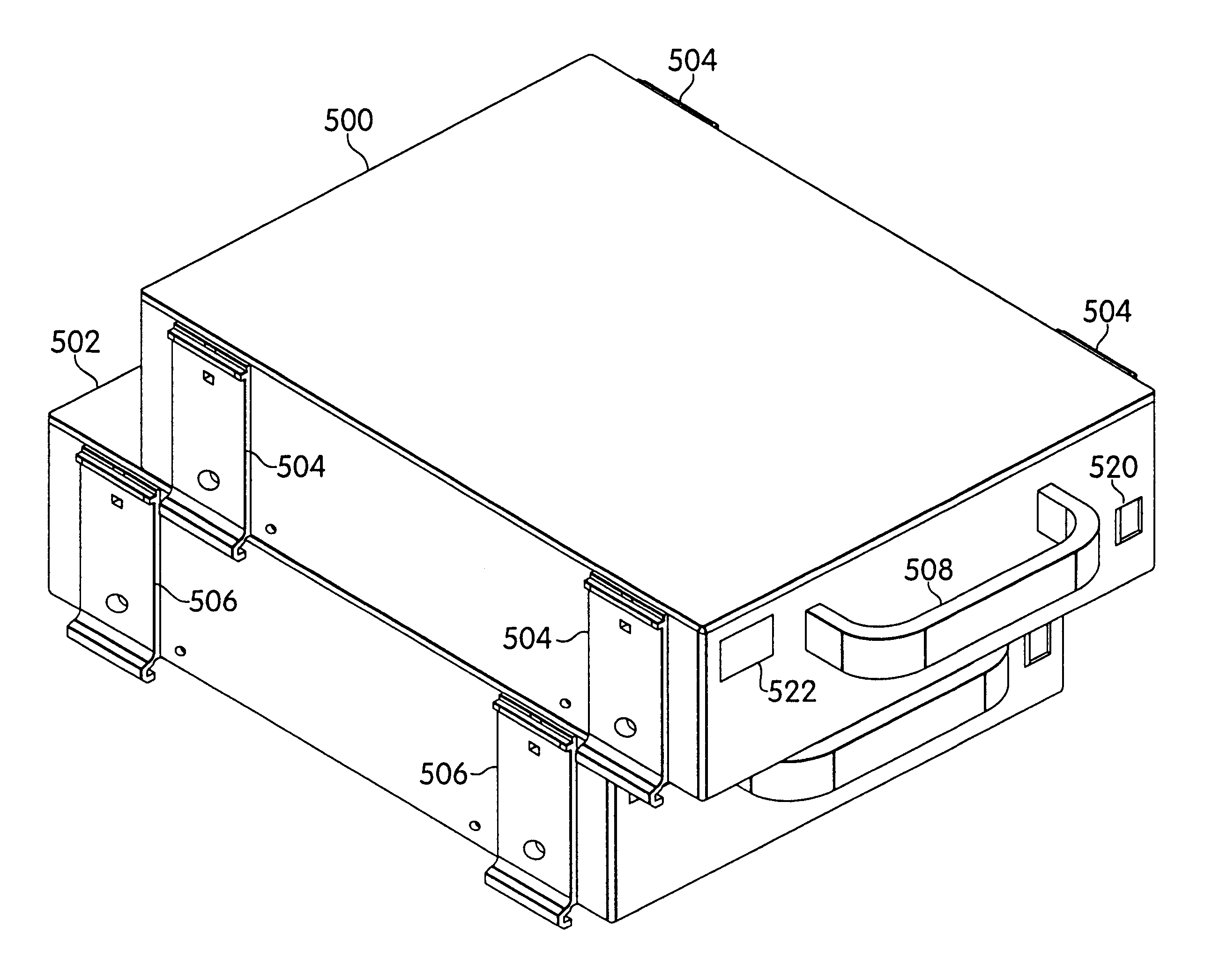
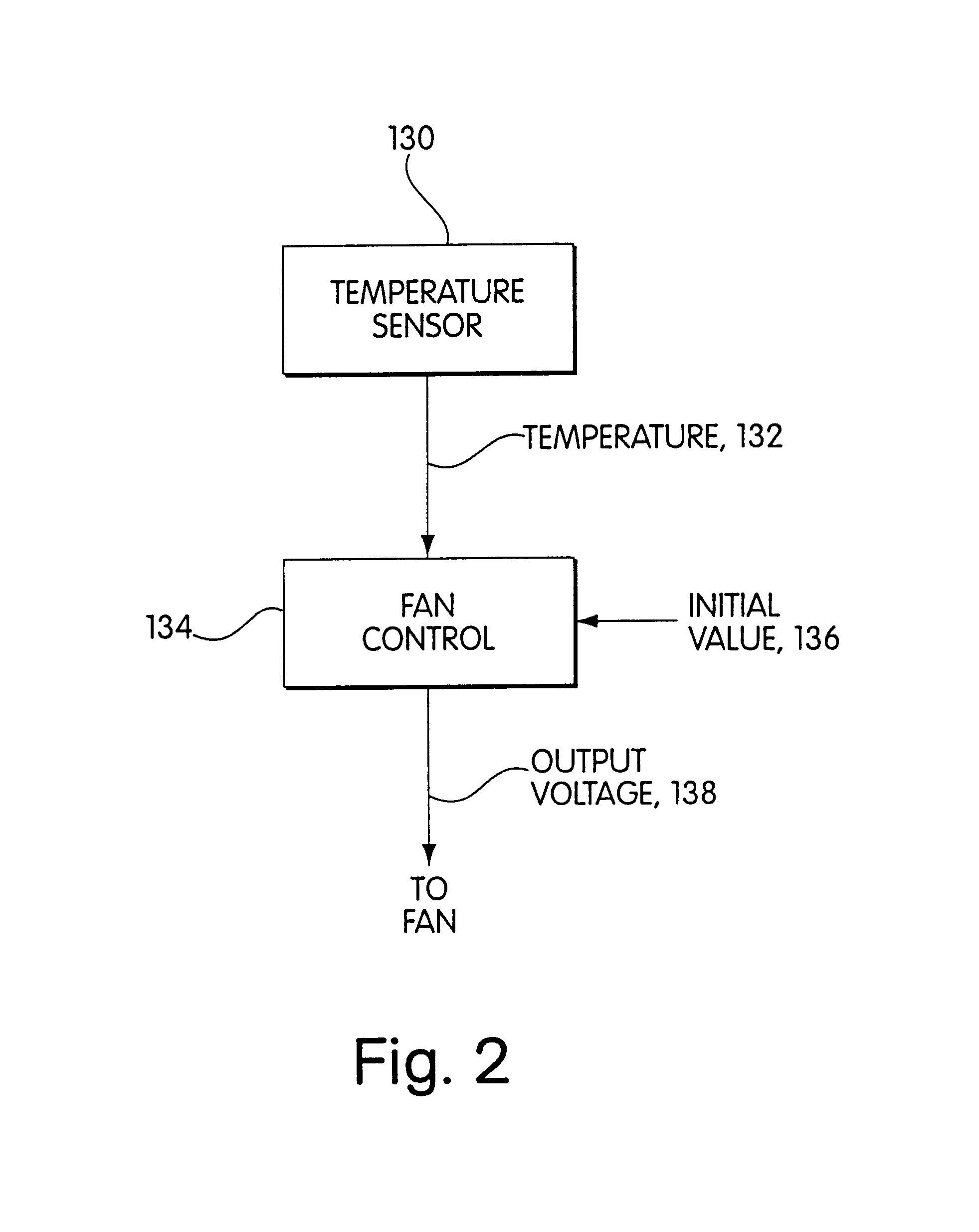
Noise is reduced in a disk drive enclosure by using vibration damping materials on the inside surface of the enclosure. These materials and their placement on the inside surface of the enclosure reduce noise without thermally insulating the disk drive. A temperature controlled fan may be used to remove heat by convection while generating a minimum amount of noise. One embodiment of an enclosure with such noise and heat reduction will be first described in connection with FIGS. 1-6.
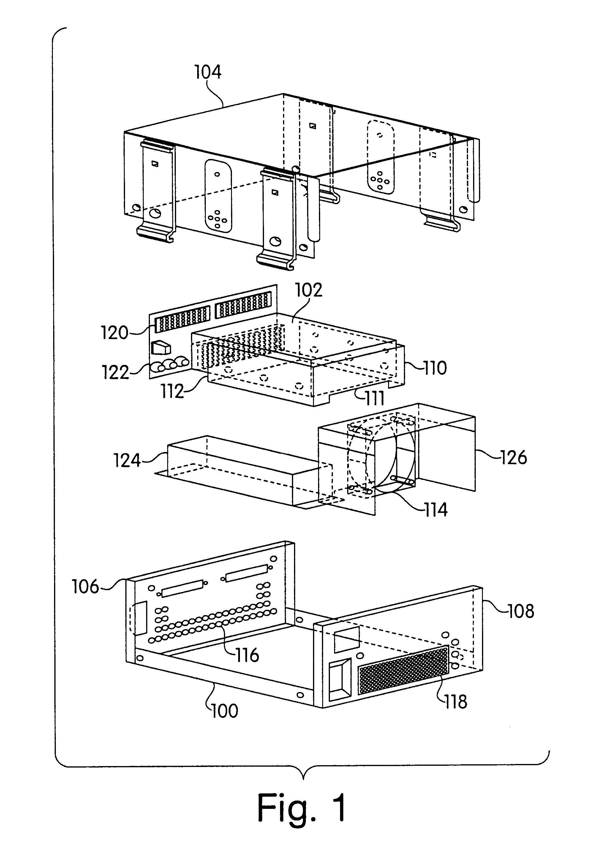
FIG. 1 is an exploded perspective view of a disk drive enclosure in one embodiment. The enclosure has a housing which, in this embodiment, is in four pieces. The housing pieces may be made of any material that is sufficiently hard and impact resistant for the environment in which the enclosure is used. Example materials include sheet metal, such as alumin...
PUM
 Abstract
Description
Claims
Application Information