Thick film heater apparatus

Inactive Publication Date: 2007-07-10
HUSKY INJECTION MOLDING SYST LTD +1
View PDF86 Cites 48 Cited by
  • Summary
  • Abstract
  • Description
  • Claims
  • Application Information

AI Technical Summary

Benefits of technology

[0018]Another aspect of the invention is to provide a thick-film heater with a unique slip-on and slip-off electrical connector feature that can survive the high temperatures and thermal expansion difficulties inherent in an injection molding machine.
[0019]Yet another aspect of the invention is to provide a more reliable heater that also exhibits a more stable and repeata

Problems solved by technology

The large metal mass responds slowly to changes in thermal input or cooling so that precise control of narrow temperature ranges is difficult to control.
Also, when temperature differences are desired in adjacent zones of the same apparatus, it is difficult to localize the particular and different temperatures to be maintained for appreciable periods of time.
This shortcoming is especially troublesome for relatively complex processing techniques and apparatus, such as in the injection molding of large parts.
Significant transitions in temperature at the point of the runner nozzle are not desirable as the nozzle is a key part of any molding process because transitions in temperature may change the fluid consistency of the melted material such as thermoplastic which may result in a defective final product.
However this type of heater configuration operates inefficiently due to heat loss because of the open exposure of the heating element to the surrounding environment.
Also, many of the standard nozzle heaters are not completely

Method used


Image

  • Thick film heater apparatus
  • Thick film heater apparatus
  • Thick film heater apparatus

Examples


Embodiment Construction

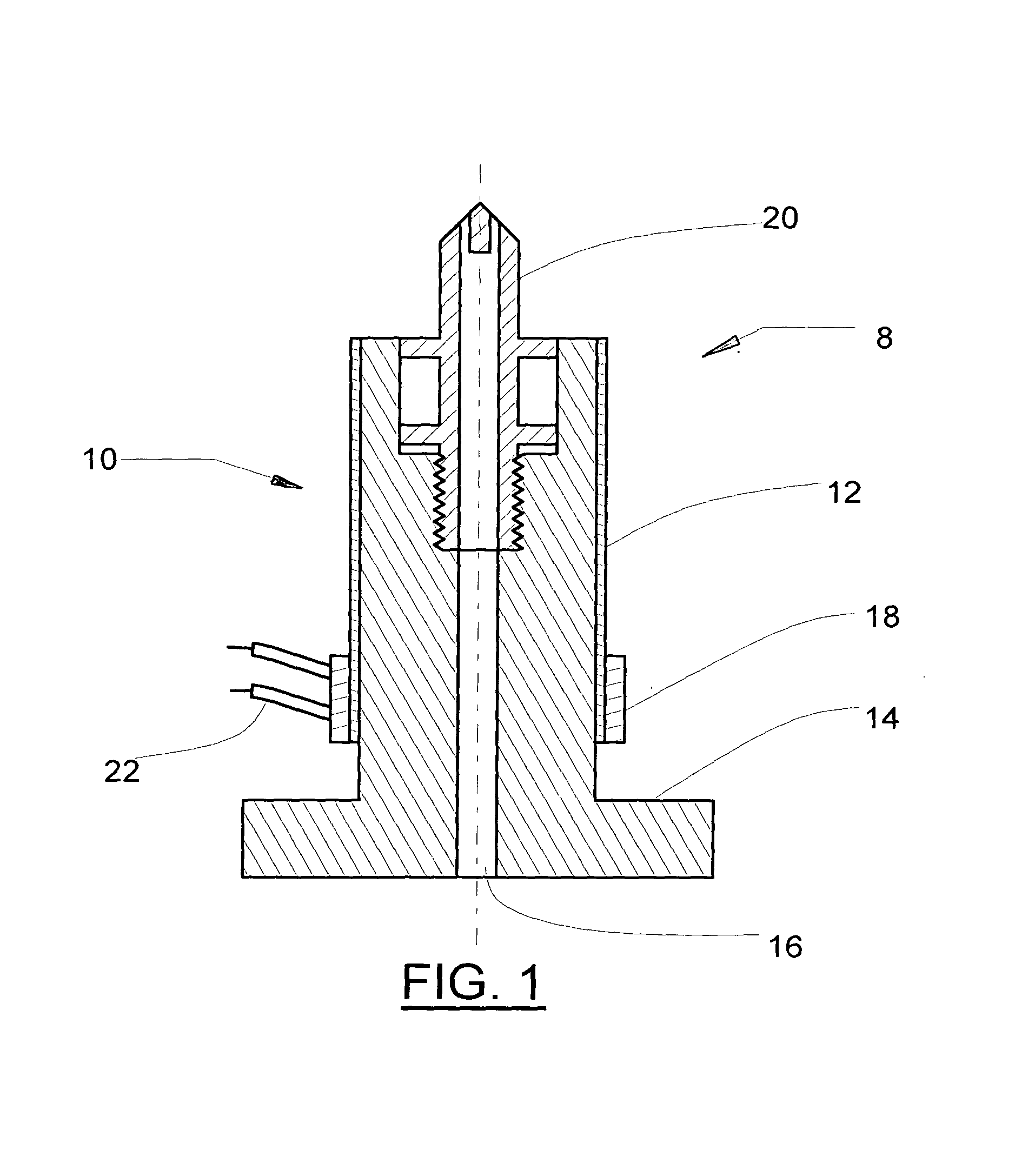
[0065]Referring to FIG. 1, a typical hot runner nozzle assembly 8 is shown. The hot runner nozzle assembly 8 comprises a nozzle body 14, a channel 16, a nozzle tip 20, a heater assembly 12, a connector sleeve assembly 18 and at least a pair of conductors 22. The channel 16 runs the length of the nozzle body 14 and communicates with the nozzle tip 20 for transfer of molten material to a mold cavity (not shown). Placed in thermal communication with the nozzle body 14 is the heater assembly 12 which maintains the material in channel 16 in a free flowing molten state. The connector sleeve assembly 18 is slidably installed over the heater assembly 12 and rigidly affixes the conductors 22 with the heater assembly 12 for communication of electrical current therethrough.

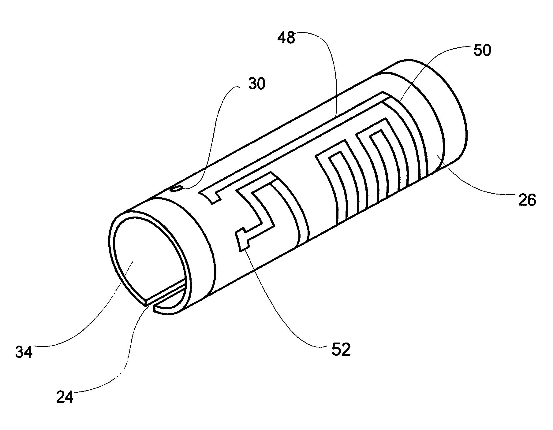
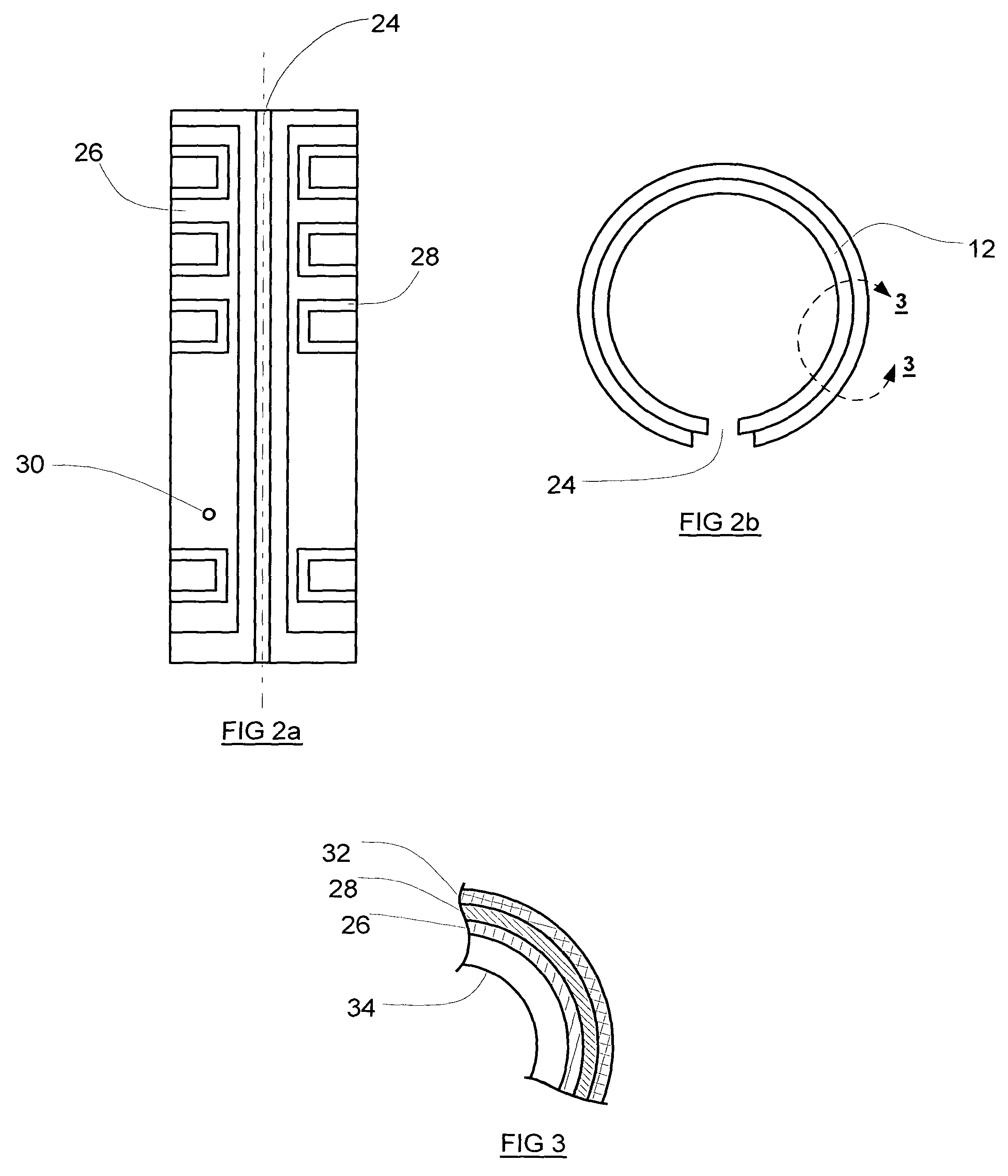
[0066]Referring now to FIGS. 2a, 2b, 2c, and FIG. 3, the heater assembly 12 is shown. The heater assembly 12 comprises an optional slot 24, a locating hole 30, a substrate 34, a thick-film dielectric layer 26, a thick-film r...


PUM

PropertyMeasurementUnit
Lengthaaaaaaaaaa
Dielectric polarization enthalpyaaaaaaaaaa
Electrical resistanceaaaaaaaaaa

Abstract

A thick-film electric heater having thick-film layers applied directly on a thermally conductive non-flat substrate. Preferably, the substrate is cylindrically shaped. A dielectric layer is silk-screened on the substrate surface. A resistive layer is silk-screened on the dielectric layer to form a circuit for the generation of heat. The resistive layer has at least one resistive trace in a pattern that is discontinuous circumferentially. At least a pair of silk-screened contact pads are applied in electrical communication with the resistive layer for electrical connection to a power source. An insulation layer is applied over the resistive layer.

Description

BACKGROUND OF THE INVENTION[0001]1. Field of the Invention[0002]The invention relates to injection molding systems and specifically to a heater for hot runner nozzles for such systems.[0003]2. Related Prior Art[0004]Common to all devices for processing thermoplastic polymeric resins are associated means for obtaining and maintaining thermoplasticity of the resin during processing, such as the shaping of the resin material into an article. Maintenance of thermoplasticity may require both heating and cooling of the resin at various times in the processing of the resin. Cooling may be needed to avoid thermal degradation of the resin. Almost all of the resin processing techniques rely at least in part on heating or cooling of the polymeric resin by thermal transfer through the agency of a metal surface, part of the processing apparatus. Heat is generally applied to an outside surface of the metal apparatus by concentrated heat sources such as band heaters, or from within the body of the...

Claims


Application Information

Patent Timeline
IPC IPC(8): B29C45/74H05B3/16B29C45/73B29C45/27
CPCB29C45/2737B29C45/74B29C2045/2745B29C2045/2746Y10S425/013B29C45/73
Inventor BOOTH, ANDREWWARREN, HAROLDWINKELMANN, WINKJENKO, EDWARDPILAVDZIC, JIM
Owner HUSKY INJECTION MOLDING SYST LTD
Why Eureka
Try Eureka