Electrical connector with ESD protection

a technology of electrical connectors and protection devices, applied in the direction of coupling device connections, coupling protective earth/shielding arrangements, two-part coupling devices, etc., can solve the problems of electrostatic discharge between the two connectors, voltage can be high enough to damage or destroy certain types of electrical devices such as semiconductor devices, and electrostatic discharge may damage or destroy the electrical devices on the circuit board

Active Publication Date: 2006-05-16
TYCO ELECTRONICS LOGISTICS AG (CH)
View PDF7 Cites 189 Cited by
  • Summary
  • Abstract
  • Description
  • Claims
  • Application Information

AI Technical Summary

Problems solved by technology

When mating the connectors, opposite charges at the connector interface may result in an electrostatic discharge between the two connectors.
Generally, very little current is associated with an electrostatic discharge; however, the voltage can be high enough to damage or destroy certain types of electrical devices such as semiconductor devices.
Consequently, when the connector contacts or terminals are electrically associated with such devices on a circuit board, the electrostatic discharge may damage or destroy the electrical devices on the circuit board.
However, the provision of such ESD shields add to the cost of the connector.
These structures also add to the cost and complexity of the connector.

Method used


Image

  • Electrical connector with ESD protection
  • Electrical connector with ESD protection
  • Electrical connector with ESD protection

Examples


Embodiment Construction

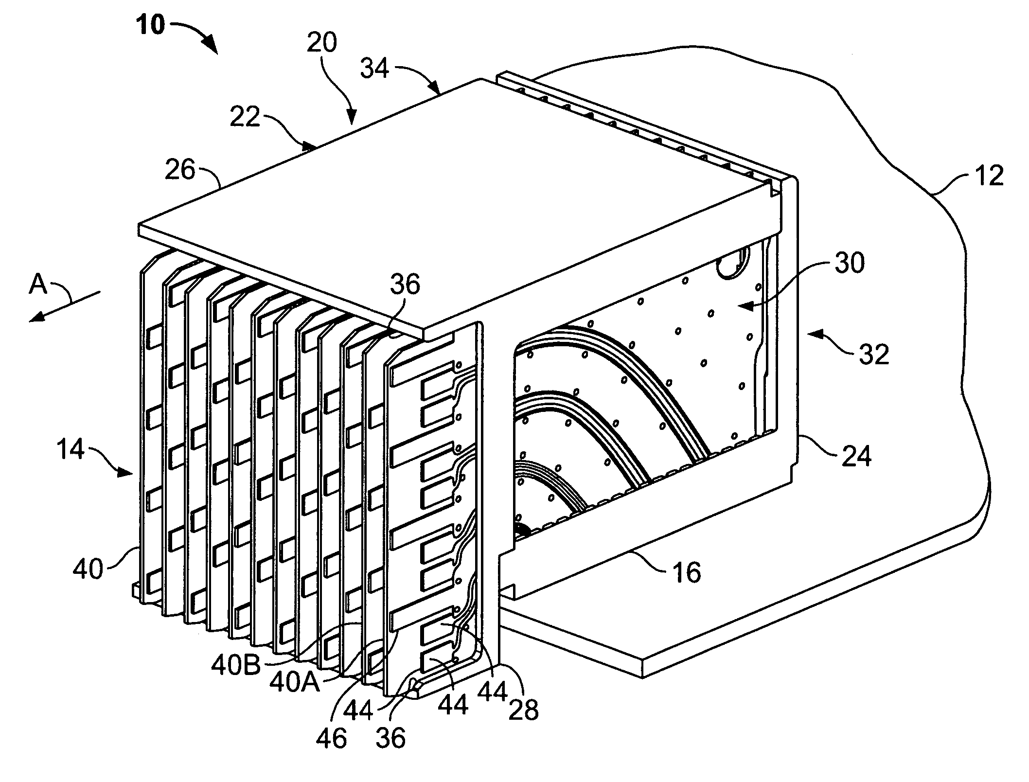
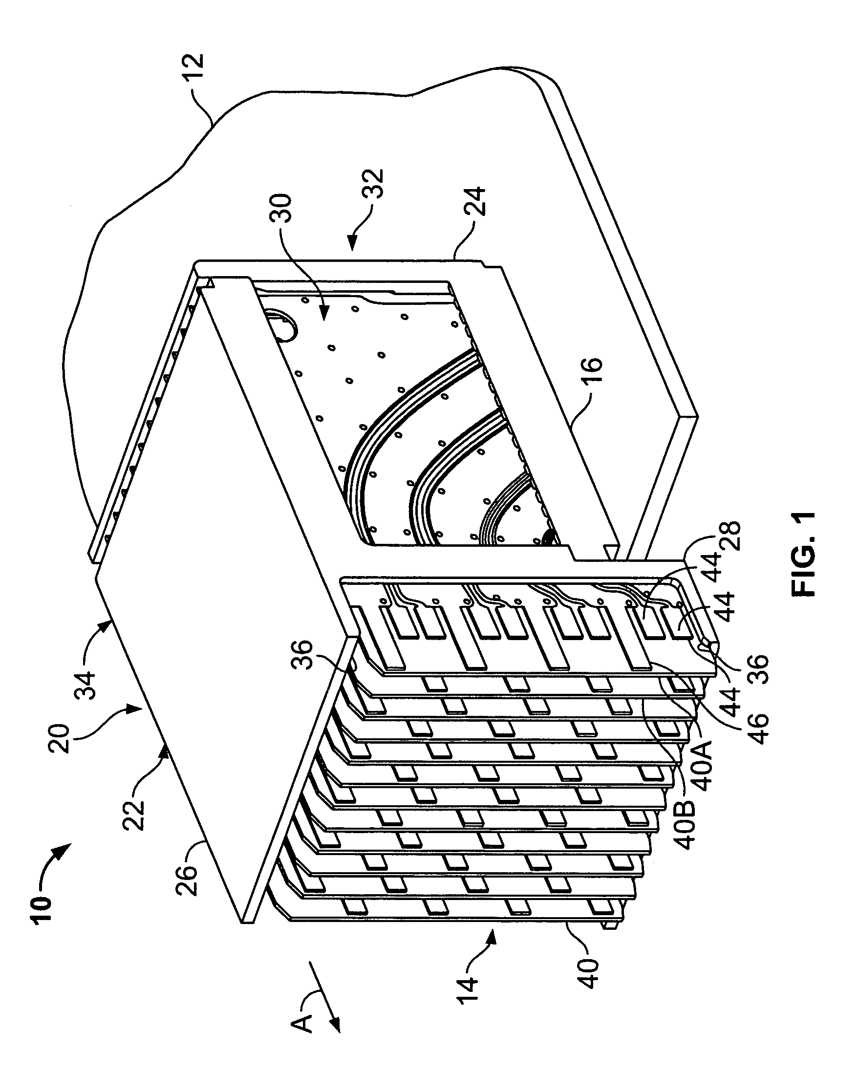
[0018]FIG. 1 illustrates a perspective view of an electrical connector 10 formed in accordance with an exemplary embodiment of the present invention. The connector 10 is a receptacle connector that is configured to be mounted on a circuit board 12 which in an exemplary embodiment is a daughter board. The connector 10 has a mating face 14 and a mounting face 16 that includes an interface for mounting the connector 10 to the circuit board 12. In an exemplary embodiment, the mounting face 16 is substantially perpendicular to the mating face 14 such that the receptacle connector 10 interconnects electrical components that are substantially at a right angle to each other. The mating face 14 of the connector 10 defines a back plane connector interface. In one embodiment, the connector 10 may be used to interconnect a daughter board to a back plane circuit board. In other embodiments, the connector 10 may be configured to interconnect electrical components that are at other than a right an...


PUM


Abstract

An electrical connector includes a dielectric housing that holds a plurality of electrical wafers. Each of the wafers includes a first side, a second side opposite the first side, and a forward mating edge. A plurality of contact pads on the first side are recessed from the forward mating edge, and a perimeter conductive trace is closer than the contact pads to the forward mating edge.

Description

BACKGROUND OF THE INVENTION[0001]This invention relates generally to electrical connectors, and more particularly, to a connector having electrostatic discharge (ESD) protection.[0002]Some electrical connectors have a mating end wherein conductive terminals are exposed for engagement with the terminals of a mating connector. This is common in a right angled connector used for interconnecting circuit boards such as a back plane and a daughter board. The back plane typically has a connector, commonly referred to as a header, that mates with a daughter board connector, commonly referred to as a receptacle. Portions of the terminals in the receptacle are often exposed for engagement with the terminals of the header connector.[0003]When mating the connectors, opposite charges at the connector interface may result in an electrostatic discharge between the two connectors. In fact, electrostatic discharges can be generated simply by a person approaching or touching the connector interface o...

Claims


Application Information

Patent Timeline
Patent Type & Authority Patents(United States)
IPC IPC(8): H01R13/648
CPCH01R13/6485H01R23/688H01R12/721H01R13/6585H01R12/00
Inventor CONSOLI, JOHN JOSEPHROTHERMEL, BRENT RYANSMITH, JR., GRAHAM HARRY
Owner TYCO ELECTRONICS LOGISTICS AG (CH)
Why Eureka
Try Eureka